Motor feedback connector pinout – Rockwell Automation 2094-EN02D-M01-Sx Kinetix 6200 and Kinetix 6500 Modular Multi-axis Servo Drives User Manual User Manual
Page 68
68
Rockwell Automation Publication 2094-UM002E-EN-P - May 2012
Chapter 4
Kinetix 6200 and Kinetix 6500 Connector Data
Figure 30 - Pin Orientation for 44-pin I/O, Safety, and Feedback (IOD) Connector
Motor Feedback Connector Pinout
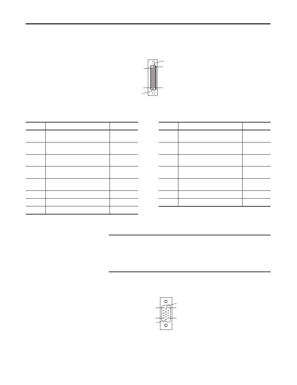
Figure 31 - Pin Orientation for 15-pin Motor Feedback (MF) Connector
Pin 30
Pin 44
Pin 1
Pin 15
Pin 16
Pin 31
44-pin Control Module
I/O, Safety, and Auxiliary Feedback
Connector
MF Pin
Description
Signal
MF Pin
Description
Signal
1
Sine differential input +
A differential input +
MTR_SIN+
MTR_AM+
9
Clock output +
MTR_CLK+
2
Sine differential input -
A differential input -
MTR_SIN-
MTR_AM-
10
Data differential input/output -
Index differential input -
MTR_DATA-
MTR_IM-
3
Cosine differential input +
B differential input +
MTR_COS+
MTR_BM+
11
Motor thermostat (normally closed)
(1)
MTR_TS
4
Cosine differential input -
B differential input -
MTR_COS-
MTR_BM-
12
Hall commutation S1 input
MTR_S1
5
Data differential input/output +
Index differential input +
MTR_DATA+
MTR_IM+
13
Hall commutation S2 input
MTR_S2
6
Encoder common
MTR_ECOM
14
Encoder 5V power output
MTR_EPWR5V
7
Encoder 9V power output
MTR_EPWR9V
15
Clock output -
MTR_CLK-
8
Hall commutation S3 input
MTR_S3
(1) Not applicable unless motor has integrated thermal protection.
IMPORTANT
Combined motor-power cable length for all axes on the same DC bus must not
exceed 240 m (787 ft) with 460V systems. Drive-to-motor power cables must
not exceed 90 m (295.5 ft).
System performance was tested at these cable length specifications. These
limitations also apply when meeting CE requirements.
Pin 11
Pin 6
Pin 15
Pin 1
Pin 10
Pin 5
15-pin Control Module
Motor Feedback Connector