Rockwell Automation 2094-EN02D-M01-Sx Kinetix 6200 and Kinetix 6500 Modular Multi-axis Servo Drives User Manual User Manual
Page 246
246
Rockwell Automation Publication 2094-UM002E-EN-P - May 2012
Appendix A
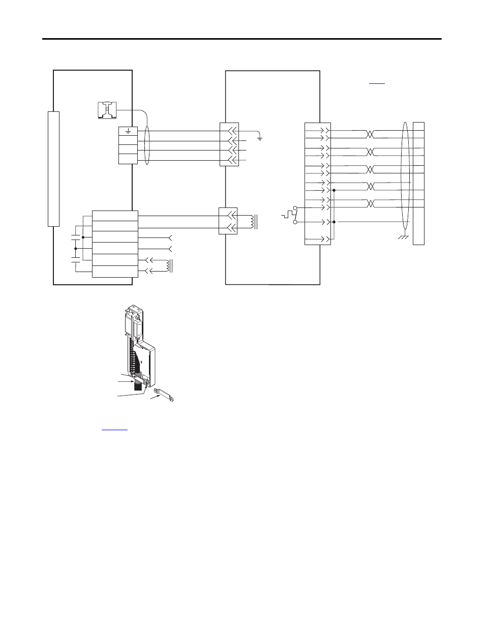
Interconnect Diagrams
Figure 107 - AM Module (460V) Wiring Examples with 1326AB Motors
D
C
B
A
BR+
BR-
A
C
W
V
U
SIN+
SIN-
COS+
COS-
DATA+
DATA-
–
ECOM
GREEN
WHT/GREEN
GRAY
WHT/GRAY
BLACK
WHT/BLACK
RED
WHT/RED
C
D
E
F
A
B
K
L
1
2
3
4
5
10
14
6
S
P
+9VDC–
TS+
ORANGE
WHT/ORANGE
N
R
7
11
4
3
2
1
6
5
4
3
2
1
Green/Yellow
1/Blue
2/Black
3/Brown
Black
White
GND
W
V
U
BR+
BR-
MBRK -
MBRK +
COM
PWR
DBRK -
DBRK +
TS-
BLUE
COM
1
2
3
4
5
6
7
8
9
10
11
12
13
14
15
Motor Brake
Resistive Brake
Connections
Motor/Resistive
Brake (BC) Connector
Motor Power
(MP) Connector
Note 10
Note 15
1326AB (M2L/S2L)
Servo Motors with
High Resolution Feedback
2090-XXxPMP-xxSxx
Motor Power Cable
Note 16
Three-phase
Motor Power
Motor Feedback
Thermostat
2090-UXxBMP-18Sxx Brake Cable
Note 16
User Supplied
24V DC
2090-XXxFMP-Sxx
(flying-lead) Feedback Cable
Notes 16, 17
Cable Shield
Clamp
Refer to low-profile connector
illustration (lower left)
for proper grounding technique.
Refer to table on
for note information.
IAM (inverter) or AM
Power Module
2090-K6CK-D15M
Connector Kit
Motor Feedback
(MF) Connector
Grounding Technique for
Feedback Cable Shield
Turn clamp over to hold
small cables secure.
Exposed shield secured
under clamp.
Clamp Screws (2)
Clamp
2090-K6CK-D15M
Low-profile Connector Kit
Refer to Low Profile Connector Kit Installation Instructions,
publication
for connector kit specifications.