External shunt modules – Rockwell Automation 2094-EN02D-M01-Sx Kinetix 6200 and Kinetix 6500 Modular Multi-axis Servo Drives User Manual User Manual
Page 51
Rockwell Automation Publication 2094-UM002E-EN-P - May 2012
51
Planning the Kinetix 6200 and Kinetix 6500 Drive System Installation
Chapter 2
External Shunt Modules
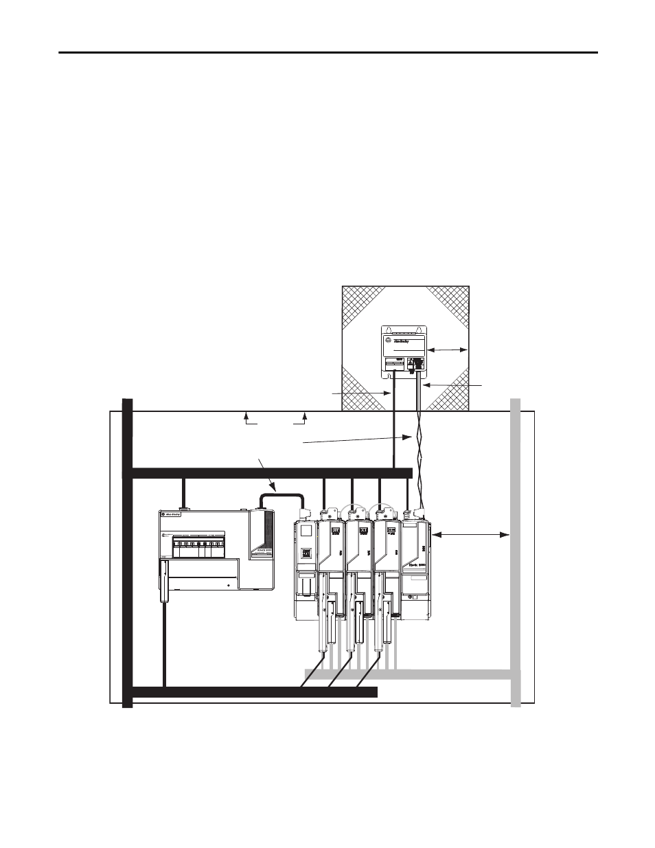
Observe these guidelines when mounting your external shunt module outside the
enclosure:
• Mount circuit components and wiring in the very dirty zone or in an
external shielded enclosure. Run shunt power and fan wiring inside metal
conduit to minimize the effects of EMI and RFI.
• Mount resistors (other than metal-clad) in a shielded and ventilated
enclosure outside the cabinet.
• Keep unshielded wiring as short as possible. Keep shunt wiring as flat to
the cabinet as possible.
• Route thermal switch and fan wires separate from shunt power.
Figure 22 - External Shunt Module Outside the Enclosure
C
D
D
D
D
D
VD
C
VD
D
1394 Digital Servo Controller
300W Shunt Module
BULLETIN 1394 300W SHUNT MODULE
ALLEN-BRADLEY
FOR USE WITH 1394-SJT22-X SYSTEM MODULE
CAT.
PART
SER.
INPUT DC
INPUT AC
FOR FUSE REPLACEMENT USE:
BUSSMAN CAT. NO.
R
Line Interface Module
Kinetix 6200 or
Kinetix 6500 System
Dirty Wireway
Clean Wireway
Motor Power Cables
Very Dirty Connections Segregated
(not in wireway)
Customer-supplied
Metal Enclosure
150 mm (6.0 in.)
clearance (min) on all four
sides of the shunt module.
Enclosure
2094-BSP2
Shunt Module
Metal Conduit
(where required
by local code)
Shunt thermal Switch and Fan Wires (when present)
No sensitive
equipment within
150 mm (6.0 in.).
Clean I/O, Feedback, and
Ethernet Cables
Dirty I/O and
Safety Cables
Shunt Power Wiring Methods:
Twisted pair in conduit (1st choice).
Shielded twisted pair (2nd choice).
Twisted pair, two twists per foot (min) (3rd choice).