Rockwell Automation 2094-EN02D-M01-Sx Kinetix 6200 and Kinetix 6500 Modular Multi-axis Servo Drives User Manual User Manual
Page 239
Rockwell Automation Publication 2094-UM002E-EN-P - May 2012
239
Interconnect Diagrams
Appendix A
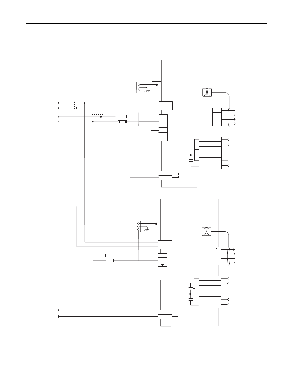
Figure 99 - Leader IAM Module with Multiple Follower IAM Modules (continued)
CONT EN-
CONT EN+
W
V
U
DC-
DC+
L3
L2
L1
CTRL 2
CTRL 1
1
2
1
2
3
4
5
6
1
2
6
5
4
3
2
1
4
3
2
1
MBRK -
MBRK +
COM
PWR
DBRK -
DBRK +
N.C.
N.C.
N.C.
CONT EN-
CONT EN+
W
V
U
DC-
DC+
L3
L2
L1
CTRL 2
CTRL 1
1
2
1
2
3
4
5
6
1
2
6
5
4
3
2
1
4
3
2
1
MBRK -
MBRK +
COM
PWR
DBRK -
DBRK +
N.C.
N.C.
N.C.
Note 4
* Indicates User Supplied Component
From Leader
Control Circuit
Connections
From Leader
Control Power
Connections
From Leader
DC Bus Connections
Control Power
(CPD) Connector
Contactor Enable
(CED) Connector
Note 14
Motor/Resistive
Brake (BC) Connector
Three-phase
Motor Power
Connections
Note 16
Motor Power
(MP) Connector
Cable Shield
Clamp
Note 10
2094-BCxx-Mxx-M
Common-bus Follower
IAM Power Module
Power Rail
Ground Stud
DC Bus
and
Three-phase
Input (IPD)
Connector
Bonded Cabinet
Ground Bus *
Note 4
Control Power
(CPD) Connector
Contactor Enable
(CED) Connector
Note 14
Motor/Resistive
Brake (BC) Connector
Three-phase
Motor Power
Connections
Note 16
Motor Power
(MP) Connector
Cable Shield
Clamp
Note 10
2094-BCxx-Mxx-M
Common-bus Follower
IAM Power Module
Power Rail
Ground Stud
DC Bus
and
Three-phase
Input (IPD)
Connector
Bonded Cabinet
Ground Bus *
DC Bus Fusing *
Note 2
DC Bus Fusing *
Note 2
Refer to table on
for note information.