Rockwell Automation 2094-EN02D-M01-Sx Kinetix 6200 and Kinetix 6500 Modular Multi-axis Servo Drives User Manual User Manual
Page 42
42
Rockwell Automation Publication 2094-UM002E-EN-P - May 2012
Chapter 2
Planning the Kinetix 6200 and Kinetix 6500 Drive System Installation
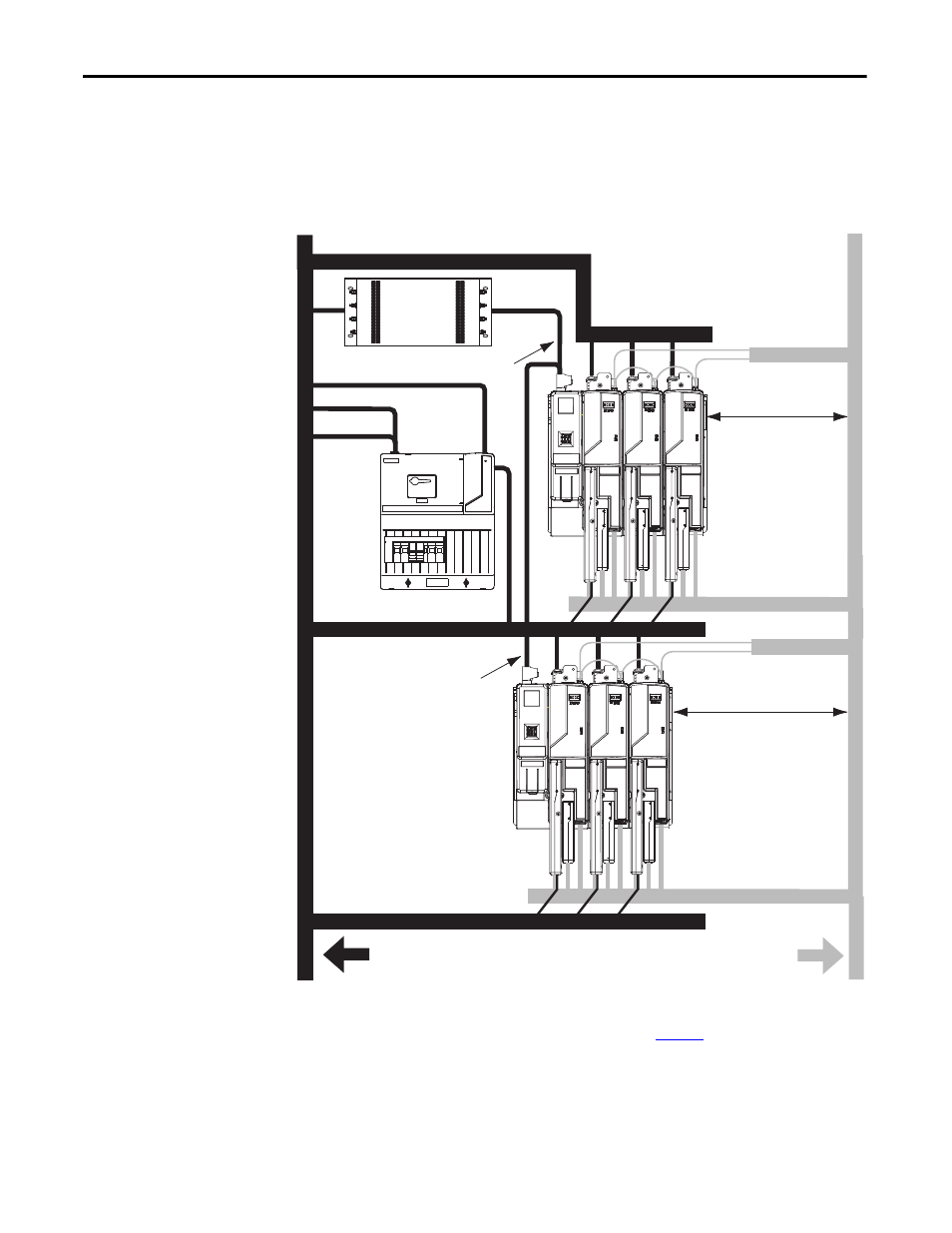
Keep the DC common-bus cable (very dirty) segregated from all other cables
(not in a wireway) when the 2094-BL
xxS or 2094-XL75S-Cx LIM module is
used in a DC common-bus configuration and the follower IAM module is
mounted below the leader IAM module.
Figure 16 - Noise Zones (DC common bus)
(1) If drive system I/O cable contains (dirty) relay wires, route cable with LIM module I/O cable in dirty wireway.
(2) When space does not permit the 150 mm (6.0 in.) segregation, use a grounded steel shield instead. For examples, refer to the
System Design for Control of Electrical Noise Reference Manual, p
C
D
VD
D
D
D
VD
D
C
VD
D
D
D
D
D
D
C
C
Line Interface Module
Kinetix 6200 or
Kinetix 6500 System
Dirty Wireway
Clean Wireway
Motor Power Cables
VAC Line, AUX VAC Output, 24V
VAC Line
AC Line Filter
(required for CE)
VAC Load
Kinetix 6200 or
Kinetix 6500 System
Very Dirty Filter/IAM Connections
Segregated (not in wireway)
Very Dirty DC Bus Connections
Segregated (not in wireway)
Fiber-optic Cable
I/O
(1)
, Feedback, and
Ethernet Cables
Route 24V DC switched signals
in shielded cable.
Route encoder, analog, registration, and
communication signals in shielded cables.
I/O
(1)
and Safety Cables
I/O
(1)
, Feedback, and
Ethernet Cables
Fiber-optic Cable
No sensitive
(2)
equipment within
150 mm (6.0 in.).
No sensitive
(2)
equipment within
150 mm (6.0 in.).