Rockwell Automation 2094-EN02D-M01-Sx Kinetix 6200 and Kinetix 6500 Modular Multi-axis Servo Drives User Manual User Manual
Page 65
Rockwell Automation Publication 2094-UM002E-EN-P - May 2012
65
Kinetix 6200 and Kinetix 6500 Connector Data
Chapter 4
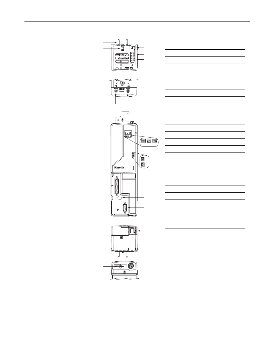
Figure 28 - Control Module Features and Indicators (sercos)
2
4
6
5
3
2
1
12
14
13
6200
6200
SAFE SPEED
7
8
9
10
11
15
4
5
15
Kinetix 6200
Control Module, Top View
(2094-SE02F-M00-S1 is shown)
Kinetix 6200
Control Module, Front View
(2094-SE02F-M00-S1 is shown)
Item
Description
1
Guide pins (2x)
2
Captive screw
3
Sercos communication rate and
optical power switches
4
Sercos transmit (Tx) Connector
(1)
(1) For the remainder of the IPIM module features and indicators, refer
to the Kinetix 6000M Integrated Drive-Motor User Manual,
publicat
5
Sercos receive (Rx) Connector
(1)
Item
Description
6
Four-character status display
7
PORT 1 status indicator
8
Drive status indicator
9
Comm status indicator
10
DC bus status indicator
11
Safety lock status indicator
(2094-SE02F-M00-S1 modules only)
12
I/O, safety, and aux feedback (IOD) connector
13
Power module mounting screw access hole
14
Motor feedback (MF) connector
Item
Description
15
Ethernet (PORT1) connector
(1)
(1) The Kinetix 6000M IPIM module has two Ethernet ports. They
provide the same function on the IPIM module as the Ethernet port
on the Kinetix 6200 control module. Refer to the Kinetix 6000M
Integrated Drive-Motor User Manual, publication
more information.
Kinetix 6200
Control Module, Bottom View
(2094-SE02F-M00-S1 is shown)
2094-SEPM-B24-S
IPIM Module, Top View
2094-SEPM-B24-S
IPIM Module, Bottom View