Rockwell Automation 2094-EN02D-M01-Sx Kinetix 6200 and Kinetix 6500 Modular Multi-axis Servo Drives User Manual User Manual
Page 249
Rockwell Automation Publication 2094-UM002E-EN-P - May 2012
249
Interconnect Diagrams
Appendix A
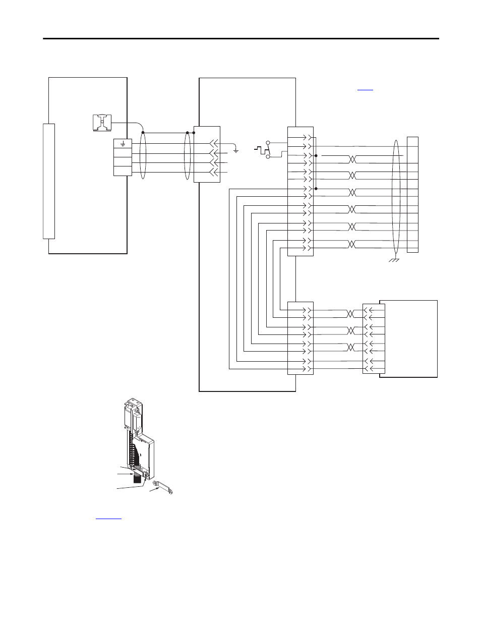
Figure 110 - AM Module with LDC-Series Linear Motors
(cable connectors)
C
B
A
W
V
U
4
3
2
1
GREEN/YELLOW
BLUE
BLACK
BROWN
GND
SHIELD
W
V
U
1
4
2
5
3
6
8
7
(AM-)
(AM+)
(BM-)
(BM+)
IM-
IM+
ECOM
+5VDC
BLUE
WHT/BLUE
WHT/GREEN
GREEN
WHT/GRAY
GRAY
WHT/BLACK
BLACK
WHT/RED
RED
TS+
TS-
S1
S2
S3
YELLOW
WHT/YELLOW
13
14
SIN-
SIN+
COS-
COS+
2
1
4
3
10
5
6
14
13
8
12
11
2
1
4
3
6
5
10
9
12
15
16
17
WHT/ORANGE
SIN+
SIN-
COS+
COS-
IM+
IM-
POWER
COM
(AM+)
(AM-)
(BM+)
(BM-)
1
2
3
4
5
6
7
8
9
10
11
12
13
14
15
Motor Power
(MP) Connector
Cable Shield
Clamp
Note 10
Note 15
LDC-Cxxxxxx-xHTx1
Linear Motor Coil with
Sin/Cos or TTL External Encoder
and Cable Connectors
Three-phase
Motor Power
Motor
Feedback
Thermostat
Refer to low profile connector
illustration (lower left)
for proper grounding technique.
Grounding Technique for
Feedback Cable Shield
Turn clamp over to hold
small cables secure.
Exposed shield secured
under clamp.
Clamp Screws (2)
Clamp
Refer to table on
for note information.
2090-XXNFMF-Sxx (standard) or
2090-CFBM7DF-CDAFxx (continuous-flex)
(flying-lead) Feedback Cable
Note 16
2090-CPWM7DF-xxAAxx
(standard)
or 2090-CPWM7DF-xxAFxx
(continuous-flex)
Motor Power Cable
Notes 16, 18
IAM (inverter) or AM
Power Module
External
Sin/Cos or (TTL)
Encoder
Motor Feedback
(MF) Connector
2090-K6CK-D15M
Connector Kit
2090-K6CK-D15M
Low-profile Connector Kit
Refer to Low Profile Connector Kit Installation Instructions,
publication
for connector kit specifications.