System block diagrams, Power rail, Smps – Rockwell Automation 2094-EN02D-M01-Sx Kinetix 6200 and Kinetix 6500 Modular Multi-axis Servo Drives User Manual User Manual
Page 253
Rockwell Automation Publication 2094-UM002E-EN-P - May 2012
253
Interconnect Diagrams
Appendix A
System Block Diagrams
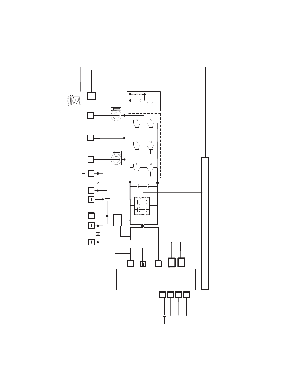
This section provides block diagrams of the Kinetix 6200 and Kinetix 6500 drive
modules. For block diagrams of the LIM module, refer to Additional Resources
on
for the documentation available for those products.
Figure 113 - IAM/AM Power Module (inverter) Block Diagram
POWER
RAIL
DC+
DC-
W
V
U
CTRL 1
CTRL 2
SY
SOK
CONV_ID (5)
GSHUNT (2)
CAN (2)
DBRK
MBRK
FUSE_OK
SMPS
PWR
Th
re
e-ph
ase Mot
or
O
utpu
t
Mo
to
r/R
esi
sti
ve B
rak
e
Co
nnec
tions
Sh
unt Ci
rc
ui
t
(4
60V on
ly)
In
ve
rt
er Sec
tion
Mo
to
r Shie
ld
C
lam
p
Co
mmon Mod
e
Chok
e
(460V only)
+/-
12V (
Contr
ol)
+24V (
Cu
st
omer
I/O
)
+
9V
, +5V (Mo
tor F
eedbac
k)
Ch
ass
is
This manual is related to the following products: