Uplink modules – Allied Telesis AlliedView-EMS 4.0.2 Device-Manager User Manual
Page 437
AlliedView™-EMS 4.0.2 Device Management Guide
Page 437 of 441
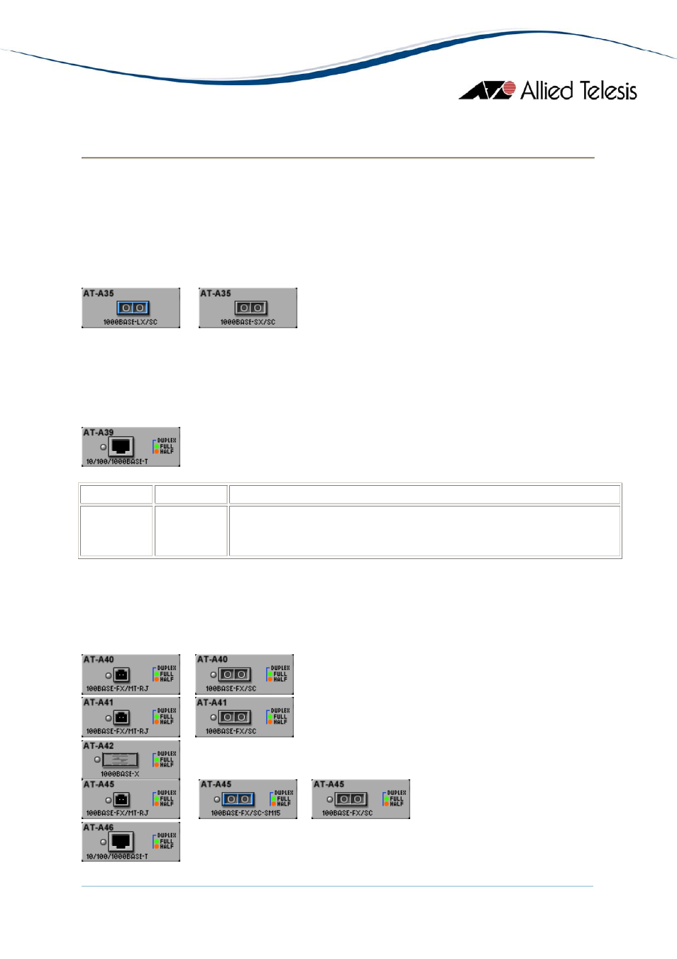
Uplink Modules
This section describes the Uplink Modules that can be installed on a switch. If one of these
uplink modules is installed in an uplink bay of a switch, it will be displayed in the uplink bay
image of the device panel in the main window. The operations available for the main device
include the ports in any of these uplink modules.
AT-A35
Note
- There are no LEDs on these modules.
AT-A39/T
LED
State
Description
DUPLEX Green
Orange
The port is operating at full-duplex.
The port is operating at half-duplex.
Note
- Earlier versions of the AT-A39/T uplink module can only operate at 1000 Mbps.
AT-A4x
See also other documents in the category Allied Telesis Computer hardware:
- AT-GS908M (54 pages)
- AT-x230-10GP (80 pages)
- AT-GS950/10PS (386 pages)
- AT-GS950/48PS (64 pages)
- AT-GS950/16PS (386 pages)
- AT-GS950/48PS (386 pages)
- AT-9000 Series (1480 pages)
- AT-9000 Series (258 pages)
- IE200 Series (70 pages)
- AT-GS950/48 (410 pages)
- AT-GS950/8 (52 pages)
- AT-GS950/48 (378 pages)
- AT-GS950/48 (60 pages)
- SwitchBlade x8106 (322 pages)
- SwitchBlade x8112 (322 pages)
- SwitchBlade x8106 (240 pages)
- SwitchBlade x8112 (240 pages)
- AT-TQ Series (172 pages)
- AlliedWare Plus Operating System Version 5.4.4C (x310-26FT,x310-26FP,x310-50FT,x310-50FP) (2220 pages)
- FS970M Series (106 pages)
- 8100L Series (116 pages)
- 8100S Series (140 pages)
- x310 Series (120 pages)
- x310 Series (116 pages)
- AT-GS950/24 (404 pages)
- AT-GS950/24 (366 pages)
- AT-GS950/16 (44 pages)
- AT-GS950/16 (364 pages)
- AT-GS950/16 (404 pages)
- AT-GS950/8 (404 pages)
- AT-GS950/8 (364 pages)
- AT-GS950/8 (52 pages)
- AT-8100 Series (330 pages)
- AT-8100 Series (1962 pages)
- AT-FS970M Series (330 pages)
- AT-FS970M Series (1938 pages)
- SwitchBlade x3106 (288 pages)
- SwitchBlade x3112 (294 pages)
- SwitchBlade x3106 (260 pages)
- SwitchBlade x3112 (222 pages)
- AT-S95 CLI (AT-8000GS Series) (397 pages)
- AT-S94 CLI (AT-8000S Series) (402 pages)
- AT-IMC1000T/SFP (23 pages)
- AT-IMC1000TP/SFP (24 pages)
- AT-SBx3106WMB (44 pages)