At-mcf2000 modules, At-mcf2000m, At-mcf2000s – Allied Telesis AlliedView-EMS 4.0.2 Device-Manager User Manual
Page 422
AlliedView™-EMS 4.0.2 Device Management Guide
Page 422 of 441
AT-MCF2000 Modules
This section describes the modules supported by Device Manager. If modules are installed
on the AT-MCF2000 chassis at the time Device Manager is called, they will be displayed in
their corresponding slots on the chassis image.
•
AT-MCF2000M
•
AT-MCF2000S
•
AT-MCF2012LC
•
AT-MCF2012LC/1
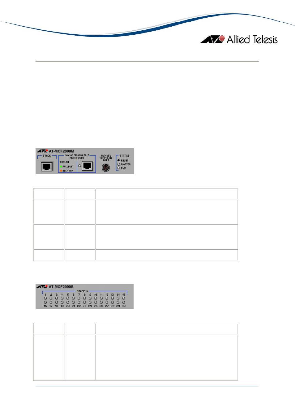
AT-MCF2000M
Management Module : 10/100/1000BASE-T
LED
State
Description
MASTER
Green
Gray
Management module chassis ID is set to 0.
Management module chassis ID is set to 31.
DUPLEX
Green
Orange
The port is operating in full-duplex mode.
The port is operating in half-duplex mode.
PWR
Green
The power supply is on.
AT-MCF2000S
Stacking Module
LED
State
Description
STACK ID
Green
Gray
Indicates that a connection has been established for the
stack module. The number that corresponds to the LED
is the stack ID.
Connection with another Stack port has not been
established.
- AT-GS908M (54 pages)
- AT-x230-10GP (80 pages)
- AT-GS950/48PS (64 pages)
- AT-GS950/10PS (386 pages)
- AT-GS950/16PS (386 pages)
- AT-GS950/48PS (386 pages)
- AT-9000 Series (258 pages)
- AT-9000 Series (1480 pages)
- IE200 Series (70 pages)
- AT-GS950/48 (378 pages)
- AT-GS950/48 (60 pages)
- AT-GS950/48 (410 pages)
- AT-GS950/8 (52 pages)
- SwitchBlade x8106 (322 pages)
- SwitchBlade x8112 (322 pages)
- SwitchBlade x8106 (240 pages)
- SwitchBlade x8112 (240 pages)
- AT-TQ Series (172 pages)
- AlliedWare Plus Operating System Version 5.4.4C (x310-26FT,x310-26FP,x310-50FT,x310-50FP) (2220 pages)
- FS970M Series (106 pages)
- 8100S Series (140 pages)
- 8100L Series (116 pages)
- x310 Series (116 pages)
- x310 Series (120 pages)
- AT-GS950/16 (44 pages)
- AT-GS950/24 (404 pages)
- AT-GS950/24 (366 pages)
- AT-GS950/16 (404 pages)
- AT-GS950/16 (364 pages)
- AT-GS950/8 (404 pages)
- AT-GS950/8 (364 pages)
- AT-GS950/8 (52 pages)
- AT-8100 Series (330 pages)
- AT-8100 Series (1962 pages)
- AT-FS970M Series (330 pages)
- AT-FS970M Series (1938 pages)
- SwitchBlade x3106 (288 pages)
- SwitchBlade x3112 (294 pages)
- SwitchBlade x3106 (260 pages)
- SwitchBlade x3112 (222 pages)
- AT-S95 CLI (AT-8000GS Series) (397 pages)
- AT-S94 CLI (AT-8000S Series) (402 pages)
- AT-IMC1000T/SFP (23 pages)
- AT-IMC1000TP/SFP (24 pages)
- AT-SBx3106WMB (44 pages)