5 uwbtracer/trainer rear panel description, 6 interchangeable radios, Figure 2.15 catc 5k rear panel – Teledyne LeCroy UWBTracer User Manual User Manual
Page 36: 5 uwb tracer/trainer rear panel description
Chapter 2: Hardware Description
UWBTracer/Trainer User Manual
18
LeCroy Corporation
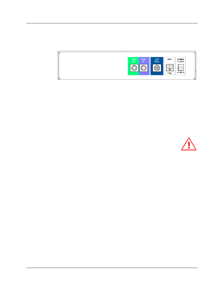
2.5 UWBTracer/Trainer Rear Panel Description
From left to right, the rear panel contains the following components:
Figure 2.15 CATC 5K Rear Panel
•
SYNC IN/OUT: For synchronized multi-analyzer operation, the analyzers must be
connected in a daisy-chain topology to each other using the green/purple cable.
•
EXT DATA: For attaching the TRIG-IN/TRIG-OUT BNC Y-cable (Trigger Cable) to
external instruments
•
HOST: For connecting the analyzer through USB to the host machine
•
POWER 12 VDC: For connecting the external power supply to the analyzer.
Note: There is no power switch on the analyzer.
Warning! Do not open the CATC 5K enclosure. No operator
serviceable parts are inside. Refer servicing to LeCroy.
2.6 Interchangeable Radios
Because WiMedia UWB specifications and technology are still evolving, a
UWBTracer/Trainer™ analyzer (with its CATC 5K platform) can use interchangeable
plug-in modules, each incorporating different PHYs (radios).
Currently there are two UWB Analyzer plug-in modules that can be used with the
UWBTracer: model UW002MA and model UW003MA.
Please note that each UWB Analyzer plug-in module requires different initialization
sequences that are executed according to a script that must be downloaded to the
analyzer using the Analyzer Setup menu and window, as described in Section 16.4,
“BusEngine, Firmware, and Plugin Init Updates” on page 280.
After you plug the module into the correct slot and check that you have the correct
BusEngine, Firmware, and initialization script installed, you can record traces.