Digital operator jvop-180 keys and displays, Yea_com, 2 using the led monitor/digital operator – Yaskawa L1000E AC Drive Technical Manual for CIMR-LE Models for Elevator Applications User Manual
Page 90
4.2 Using the LED Monitor/Digital Operator
90
YASKAWA ELECTRIC SIEP YAIL1E 01A YASKAWA AC Drive L1000E Technical Manual
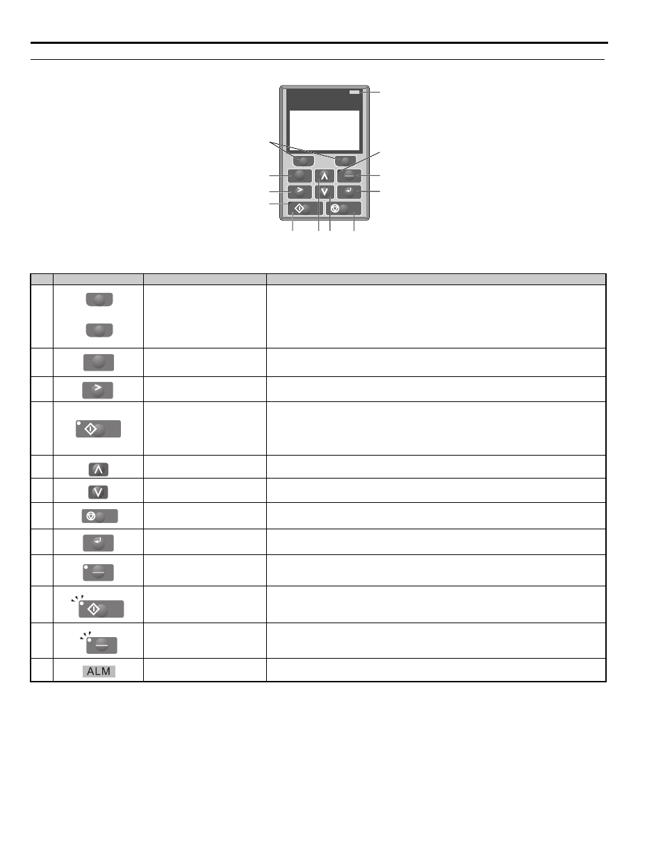
◆ Digital Operator JVOP-180 Keys and Displays
Figure 4.5
Figure 4.5 Keys and Displays on the Digital Operator
No.
<1> The STOP key has highest priority. Pressing the STOP key will always cause the drive to stop the motor, even if an Up/Down command is
active at any external Up/Down command source. To disable the STOP key priority, set parameter o2-02 to 0.
<2> The LO/RE key can only switch between LOCAL and REMOTE when the drive is stopped. By default settings the LO/RE key function is
disabled. To allow using the LO/RE key for switching between LOCAL and REMOTE, set parameter o2-01 to 1.
Display
Name
Function
1
Function Key
(F1, F2)
The functions assigned to F1 and F2 vary depending on the currently displayed menu. The name of each func-
tion appears in the lower half of the display window.
2
ESC Key
• Returns to the previous display.
• Moves the cursor one space to the left.
• Pressing and holding this button will return to the Speed Reference display.
3
RESET Key
• Moves the cursor to the right.
• Resets the drive to clear a fault situation.
4
RUN Key
Starts the drive in the LOCAL mode.
The Run LED
• is on, when the drive is operating the motor.
• flashes during deceleration to stop or when the speed reference is 0.
• flashes quickly, the drive is disabled by a DI, the drive was stopped using a fast stop DI, or an Up/Down
command was active during power up.
5
Up Arrow Key
Scrolls up to display the next item, select parameter numbers, and increment setting values.
6
Down Arrow Key
Scrolls down to display the previous item, select parameter numbers, and decrements setting values.
7
STOP Key
Stops drive operation.
8
ENTER Key
• Enters parameter values and settings.
• Selects a menu item to move between displays.
9
LO/RE Selection Key
Switches drive control between the operator (LOCAL) and the control circuit terminals (REMOTE) for the
Run command and speed reference. The LED is on when the drive is in the LOCAL mode (operation from
keypad).
10
RUN Light
Lit while the drive is operating the motor. Refer to page
for details.
11
LO/RE Light
Lit while the operator is selected to run the drive (LOCAL mode). Refer to page
for details.
12
ALM LED Light
Refer to ALARM (ALM) LED Displays on page 92
.
LO
RE
F2
F1
ESC
RUN
STOP
ENTER
RESET
ALM
DIGITAL OPERATOR JVOP-180
12
11
9
8
1
2
3
10
4
5 6
7
YEA_com
F1
F2
ESC
RESET
RUN
STOP
ENTER
LO
RE
RUN
LO
RE