H3: multi-function analog inputs, H3-01: terminal a1 signal level selection, H3-02: terminal a1 function selection – Yaskawa L1000E AC Drive Technical Manual for CIMR-LE Models for Elevator Applications User Manual
Page 207: Common_tm
5.7 H: Terminal Functions
YASKAWA ELECTRIC SIEP YAIL1E 01A YASKAWA AC Drive L1000E Technical Manual
207
P
a
ra
me
te
r De
ta
ils
5
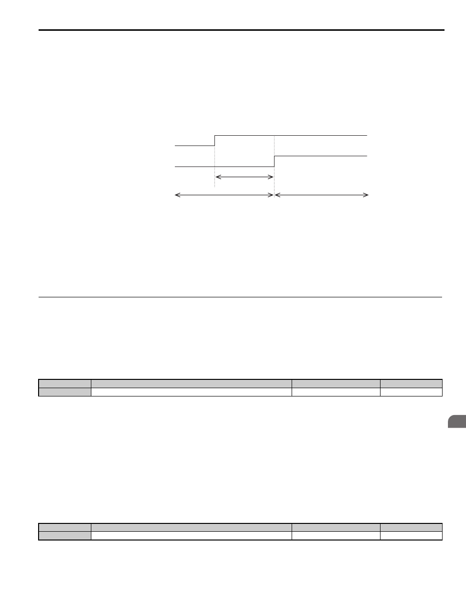
Setting 61: Motor pole search status
This terminal changes states when the Initial Motor Pole Position Search is finished.
Position Detection Selection on page 236
for details on Motor Pole Position Search.
Use this setting in applications where the motor speed feedback is supplied from a non-absolute encoder (e.g.,
incremental) and where the drive brake sequence is not utilized.
Design the external brake sequence to interlock the brake as long as the Motor Pole Position Search has not finished. In
this case, the external brake sequence should be designed to interlock the brake during Motor Pole Position Search.
Setting 100 to 161: Functions 0 to 61 with Inverse Output
These settings have the same function as settings 0 to 61 but with inverse output. Set as 1, where the “1” indicates
inverse output and the last two digits specify the setting number of the function.
Examples:
• For inverse output of “8: During baseblock”, set 108.
◆ H3: Multi-Function Analog Inputs
The drive is equipped with two multi-function analog input terminals: A1 and A2. Refer to
for a listing of the
functions that can be set to these terminals.
■
H3-01: Terminal A1 Signal Level Selection
Selects the input signal level for analog input A1.
Setting 0: 0 to 10 Vdc
The input level is 0 to 10 Vdc. The minimum input level is limited to 0%, so that a negative input signal due to gain and
bias settings will be read as 0%.
Setting 1: –10 to 10 Vdc
The input level is –10 to 10 Vdc. If the resulting voltage is negative after being adjusted by gain and bias settings, then the
motor will rotate in reverse.
■
H3-02: Terminal A1 Function Selection
Selects the input signal level for analog input A1. Refer to
Multi-Function Analog Input Terminal Settings on page 209
for instructions on how to adjust the signal level.
<1> The search process takes 0.5 to 5.0 s depending on the Motor Pole Position Search method selected in n8-35 and whether Motor Pole
Search Error detection is enabled in parameter n8-86.
No.
Parameter Name
Setting Range
Default
H3-01
Terminal A1 Signal Level Selection
0 or 1
0
No.
Parameter Name
Setting Range
Default
H3-02
Terminal A1 Function Selection
0 to 1F
0
Up/Down command
Motor pole search status
Brake interlock
Brake can be released
Motor pole position
search process
<1>
common_TM