Occurred. refer to, For a complete list of u3, U3: fault history – Yaskawa L1000E AC Drive Technical Manual for CIMR-LE Models for Elevator Applications User Manual
Page 407: U4: maintenance monitors, B.3 parameter table
B.3 Parameter Table
YASKAWA ELECTRIC SIEP YAIL1E 01A YASKAWA AC Drive L1000E Technical Manual
407
Pa
ra
met
er
L
is
t
B
■
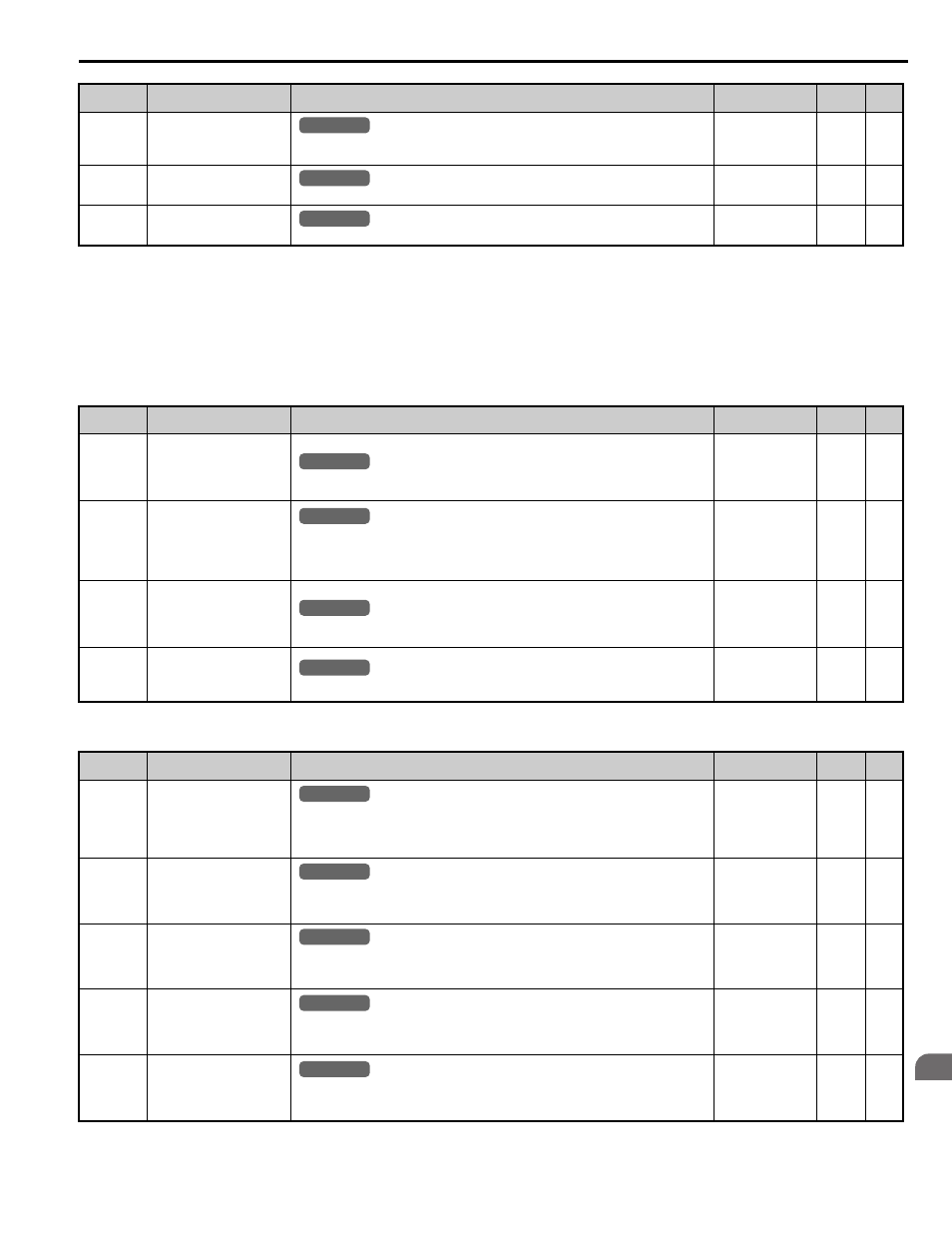
U3: Fault History
■
U4: Maintenance Monitors
U2-20
(8EH)
Heatsink Temperature at
Previous Fault
Displays the temperature of the heatsink when the most recent fault occurred. Displayed as in
U4-08.
No signal output
available
1
°C
–
U2-21
(7E6H)
Peak Hold Current during
Fault
Displays the peak current that occurred just prior to the previous fault.
No signal output
available
0.01 A
–
U2-22
(7E7H)
Peak Hold Frequency during
Fault
Displays the output frequency when the peak current displayed in U2-21 occurred.
No signal output
available
0.01 Hz
–
<10> The display resolution depends on the rated output power of the drive. Models 2A0018 to 2A0041 and 4A0009 to 4A0023 display values in
0.01 A units, while models 2A0059 to 2A0432 and 4A0030 to 4A0260 display values in 0.1 A units.
<31> Setting units are determined by the digital operator display unit selection (o1-03). When o1-03 = 0, the value is set in Hertz. When o1-03 = 4
or 5, the value is displayed in m/s. When o1-03 = 6, the value is displayed in ft/min.
<40> When checking the values of U1-03, U2-05 and U4-13 with the digital operator they are displayed in units of amperes, but when they are
checked using MEMOBUS communications, the monitor value in MEMOBUS communications is: displayed numeric value / 8192
× drive’s
rated current (A), from the condition “8192 (maximum value) = drive’s rated current (A)”.
No. (Addr.)
Name
Description
Analog Output
Level
Unit
Page
U3-01 to
U3-04
(90H to 93H
(800H to
803H))
First to 4th Most Recent Fault
Displays the first to the fourth most recent faults.
No signal output
available
–
–
U3-05 to
U3-10
(804H to
809H)
5th to 10th Most Recent Fault
Displays the fifth to the tenth most recent faults.
After ten faults have occurred in the drive, data for the oldest fault is deleted. The most recent
fault appears in U3-01, with the next most recent fault appearing in U3-02. The data is moved to
the next monitor parameter every time a fault occurs.
No signal output
available
–
–
U3-11 to
U3-14
(94H to 97H
(80AH to
80DH))
Cumulative Operation Time at
1st to 4th Most Recent Fault
Displays the cumulative operation time when the first to the fourth most recent faults occurred.
No signal output
available
1 h
–
U3-15 to
U3-20
(80EH to
813H)
Cumulative Operation Time at
5th to 10th Most Recent Fault
Displays the cumulative operation time when the fifth to the tenth most recent faults occurred.
No signal output
available
1 h
–
No. (Addr.)
Name
Description
Analog Output
Level
Unit
Page
U4-01
(4CH, 98H,
99H)
Cumulative Operation Time
Displays the cumulative operation time of the drive. The value for the cumulative operation
time counter can be reset in parameter o4-01. Use parameter o4-02 to determine if the operation
time should start as soon as the power is switched on or only while the Up/Down command is
present. The maximum number displayed is 99999, after which the value is reset to 0.
No signal output
available
1 h
–
U4-03
(67H, 94H,
9BH)
Cooling Fan Operation Time
Displays the cumulative operation time of the cooling fan. The default value for the fan
operation time is reset in parameter o4-03. This value will reset to 0 and start counting again
after reaching 99999.
No signal output
available
1 h
–
U4-04
(7EH)
Cooling Fan Maintenance
Displays main cooling fan usage time in as a percentage of its expected performance life.
Parameter o4-03 can be used to reset this monitor. The fan should be replaced when this
monitor reaches 90%.
No signal output
available
1%
–
U4-05
(7CH)
Capacitor Maintenance
Displays main circuit capacitor usage time in as a percentage of their expected performance life.
The capacitors should be replaced when this monitor reaches 90%. Parameter o4-05 can be used
to reset this monitor.
No signal output
available
1%
–
U4-06
(7D6H)
Soft Charge Bypass Relay
Maintenance
Displays the soft charge bypass relay maintenance time as a percentage of its estimated
performance life. The soft charge relay should be replaced when this monitor reaches 90%.
Parameter o4-07 can be used to reset this monitor.
No signal output
available
1%
–
No. (Addr.)
Name
Description
Analog Output
Level
Unit
Page
All Modes
common
_
All Modes
common
_
All Modes
common
_
All Modes
common
_
All Modes
common
_
All Modes
common
_
All Modes
common
_
All Modes
common
_
All Modes
common
_
All Modes
common
_
All Modes
common
_
All Modes
common
_