6 setup procedure for elevator applications, Starting rescue operation 1, Ending rescue operation 1 – Yaskawa L1000E AC Drive Technical Manual for CIMR-LE Models for Elevator Applications User Manual
Page 134
4.6 Setup Procedure for Elevator Applications
134
YASKAWA ELECTRIC SIEP YAIL1E 01A YASKAWA AC Drive L1000E Technical Manual
• Use a battery with a voltage higher than 250 Vdc for 200 V class drives or 500 Vdc for 400 V class drives and connect
it to the control power supply input (CN19). Alternatively use a 24 Vdc battery and an optional 24 V Backup Power
Supply Unit.
• Enable Light Load Direction Search (S4-01 = 1).
■
Using Separate Batteries for DC Bus and Control Power Supply, DC Bus Battery under 250
Vdc (500 Vdc)
Follow these instructions when using separate batteries for Rescue Operation with the battery for the DC bus having a
lower voltage than 250 Vdc for 200 V class drives and 500 Vdc for 400V class drives.
Wiring
Follow the wiring diagram shown in
. When connecting the battery for the control power supply to the
L1000E, use the 1.1 m cable packaged with the product. The connector cover must first be removed in order to access
connection port CN19 for the battery. Refer to
Connecting the Drive and Battery on page 137
Figure 4.21
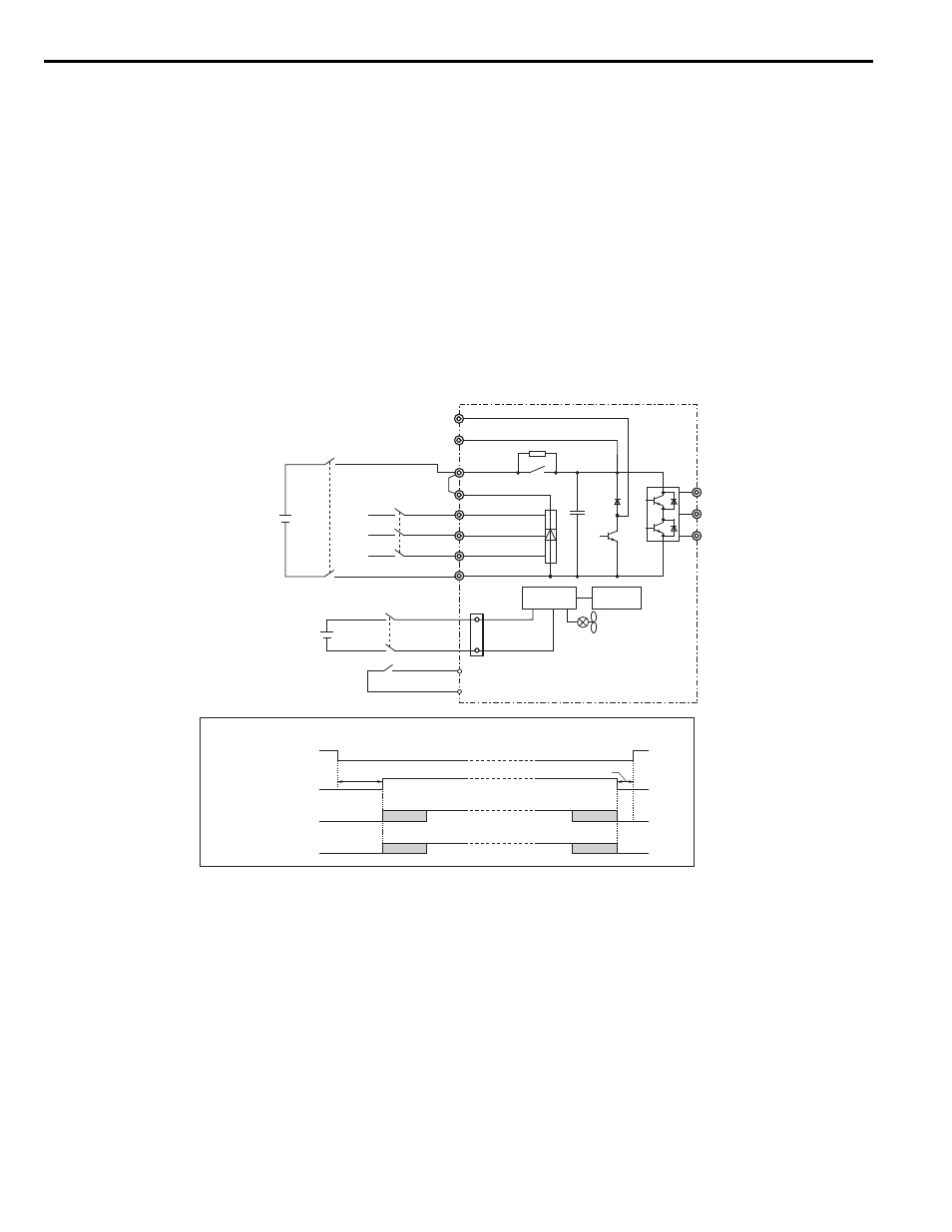
Figure 4.26 Wiring Two Batteries for DC Bus and Control Power Supply (DC Bus Battery is less than 250 V)
Operation Sequence
Starting Rescue Operation
1.
Open contactor B and wait at least 5 seconds.
2.
Set the input terminal programmed for Rescue Operation (H1- = 55).
3.
Close contactors A and C.
4.
Set the Up/Down command.
Ending Rescue Operation
1.
After the car has stopped, open contactors A and C.
2.
Clear the input terminal set for Rescue Operation (H1- = 55).
3.
Wait at least 0.5 s and then close contactor B to return to operation with normal power supply.
-
Magnetic Contactor Sequence
L1000E
Control
circuit
Power supply
Battery for DC bus
DC bus power supply
Battery for
control circuit
L1
L2
L3
CN19
1
4
W/T3
V/T2
U/T1
R/L1
S/L2
T/L3
B1
+2
+1
B2
SC
H1-
ڧڧ = 55
(Rescue Operation)
S
3
to S
8
48 to 340 Vdc
96 to 680 Vdc
250 to 340 Vdc
(500 to 680 Vdc
Magnetic Contactor A
Magnetic Contactor B
Magnetic Contactor C
H1-
ڧڧ = 55
(Rescue Operation)
Magnetic Contactor B
Magnetic Contactor A
Magnetic Contactor C
5 s
0.5 s