Installing a braking unit: cdbr type, Yea_ tmonly, 5 installing peripheral devices – Yaskawa L1000E AC Drive Technical Manual for CIMR-LE Models for Elevator Applications User Manual
Page 348
8.5 Installing Peripheral Devices
348
YASKAWA ELECTRIC SIEP YAIL1E 01A YASKAWA AC Drive L1000E Technical Manual
■
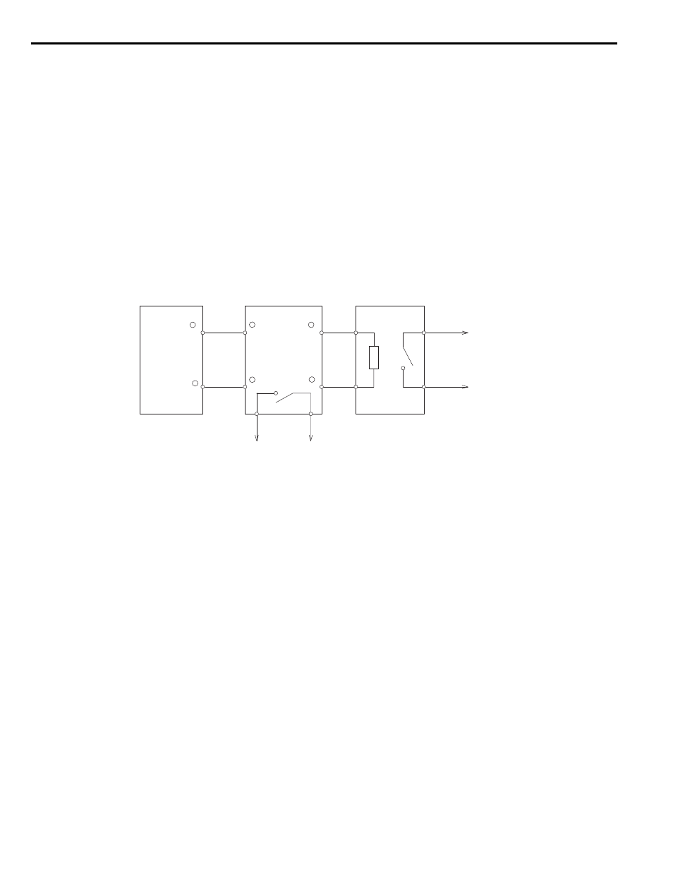
Installing a Braking Unit: CDBR Type
When using a CDBR braking unit or any other external braking transistor or a regenerative converter, disable the internal
braking transistor protection function by setting parameter L8-55 to 0.
To install a CDBR type braking unit, connect either the B1 terminal of the drive (2A0018 through 2A0144 and 4A0009
through 4A0075) or +3 terminal of the drive (2A0181 to 2A0432 and 4A0094 to 4A0260) to the positive terminal on the
braking unit. Then, wire the negative terminals on the drive and braking unit together. Terminal +2 is not used.
Connect the braking resistor to CDBR terminals +0 and -0.
Wire the thermal overload relay contact of the CDBR and the braking resistor in series, and connect this signal to a drive
digital input. Use this input to trigger a fault in the drive in case a CDBR or braking resistor overload occurs.
Disable dynamic braking transistor protection by setting L8-55 = 0.
Note: To install a CDBR type braking unit to the drive with built-in dynamic braking transistor (2A0018 through 2A0144 and 4A0009
through 4A0075), connect the B1 terminal on the drive to the positive terminal on the braking unit. Then wire the negative
terminals on the drive and braking unit together. Terminal B2 is not used.
Figure 8.14
Figure 8.16 Connecting a Braking Unit (CDBR type) and Braking Resistor Unit
(2A0181 to 2A0432 and 4A0094 to 4A0260)
Thermal
Trip Contact
Drive
Braking Unit
(CDBR type)
Braking Resistor Unit
(LKEB type)
Thermal Overload
Trip Contact
1
2
P
3
4
3
+
+ 0
−
− 0
B
+
−
YEA_
TMonly