4 option card installation, Pg encoder cables for pg-b3 option – Yaskawa L1000E AC Drive Technical Manual for CIMR-LE Models for Elevator Applications User Manual
Page 343
8.4 Option Card Installation
YASKAWA ELECTRIC SIEP YAIL1E 01A YASKAWA AC Drive L1000E Technical Manual
343
Per
iphe
ra
l De
vi
ce
s &
Optio
n
s
8
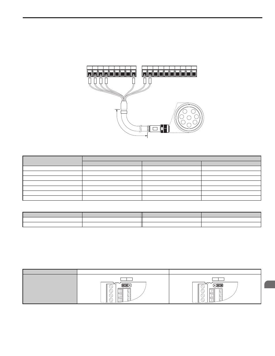
PG Encoder Cables for PG-B3 Option
Yaskawa recommends using a LMA-
B-S185Y (complementary output) for cables running between the PG-B3
Option and the PG as show in
For instructions on wiring the terminal block, refer to
.
Figure 8.8
Figure 8.10 Wiring PG Encoder Cable
Table 8.3 Connecting the PG Encoder Cable Specification
Table 8.4 PG Encoder Cable Types
6.
For the PG-X3 Option, set the voltage for the PG encoder power supply using jumper CN3 located on the option.
Position the jumper as shown in
NOTICE: The positioning of jumper CN3 selects the PG encoder power supply voltage (5.5 V or 12 V). Select the voltage level for the
PG encoder connected to the option and motor. If the wrong voltage is selected, the PG encoder may not operate properly or may
become damaged as a result.
Table 8.5 Setting the PG Encoder Power Supply Voltage (IP) with Jumper CN3
Option Terminal
PG Encoder Cable
Wire
Color
Pin
IP
1
Blue
C
IG
2
White
H
A+
3
Yellow
B
A–
4
White
G
B+
5
Green
A
B–
6
White
F
FE
E
N/A (shield)
D
Length
Type
Length
Type
10 m (32 ft.)
W5010
50 m (164 ft.)
W5050
30 m (98 ft.)
W5030
100 m (328 ft.)
W5100
Voltage Level
5.5 V ± 5% (default)
12.0 V ± 5%
Jumper CN3
A+ A- B+ B- Z+ Z-
SD FE
IP IG AO IG BO IG ZO IG
L
A
B
C
D
E
F
G
H
TA1
TB1
TB2
(Pin)
3
4
5
6
E
1
2
PG encoder side
B
3
CN3
5.5 V 12 V
CN3
5.5 V 12 V