3 c: tuning, C1: acceleration and deceleration ramps, Common_tmo – Yaskawa L1000E AC Drive Technical Manual for CIMR-LE Models for Elevator Applications User Manual
Page 162: Switching acceleration ramps by digital input
162
YASKAWA ELECTRIC SIEP YAIL1E 01A YASKAWA AC Drive L1000E Technical Manual
5.3 C: Tuning
5.3 C: Tuning
C parameters set the characteristics for acceleration, deceleration, and Jerk. Other parameters in the C group cover
settings for slip compensation, torque compensation, and carrier frequency.
◆ C1: Acceleration and Deceleration Ramps
■
C1-01 to C1-08: Accel, Decel Ramps 1 to 4
Four different sets of acceleration and deceleration times can be set in the drive by digital inputs, motor selection, or
switched automatically. Acceleration ramp parameters always set the ramp or time to accelerate from 0 to the maximum
speed. Deceleration ramp parameters always set the ramp or time to decelerate from the maximum speed to 0. C1-01 and
C1-02 are the default active accel/decel settings.
Switching Acceleration Ramps by Digital Input
Accel/decel ramps 1 are active by default if no input is set. The accel/decel ramps 2, 3, and 4 can be activated by digital
inputs (H1- = 7 and 1A) as explained in
.
Table 5.6 Accel/Decel Ramp Selection by Digital Input
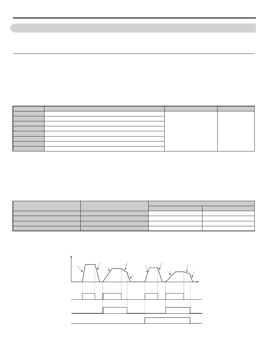
shows an operation example for changing accel/decel ramps. The example below requires that the stopping
method be set for “Ramp to stop” (b1-03 = 0).
Figure 5.5
Figure 5.5 Timing Diagram of Accel/Decel Ramp Change
No.
<1> The setting range and default value depend on the display units set in parameter o1-03. If o1-03 is set between 0 and 4, the time required to go
from 0% speed to 100% maximum speed is expressed in seconds. If o1-03 is set to 5 or 6, then setting units will appear in m/s
2
or ft/s
2
. If the
drive is in V/f control mode the accel/decel ramps can be set in seconds only.
Parameter Name
Setting Range
Default
C1-01
Acceleration Ramp 1
0.00 to 600.00 s
1.50 s
C1-02
Deceleration Ramp 1
C1-03
Acceleration Ramp 2
C1-04
Deceleration Ramp 2
C1-05
Acceleration Ramp 3(Motor 2 Accel Time 1)
C1-06
Deceleration Ramp 3(Motor 2 Decel Time 1)
C1-07
Acceleration Ramp 4(Motor 2 Accel Time 2)
C1-08
Deceleration Ramp 4(Motor 2 Decel Time 2)
Accel/Decel Ramp Sel. 1
H1- = 7
Accel/Decel Ramp Sel. 2
H1- = 1A
Active Ramps
Acceleration
Deceleration
0
0
C1-01
C1-02
1
0
C1-03
C1-04
0
1
C1-05
C1-06
1
1
C1-07
C1-08
Output
speed
Accel Ramp 1
(C1-01)
Decel Ramp 1
(C1-02)
Accel Ramp 2
(C1-03)
Decel Ramp 2
(C1-04)
Decel Ramp 1
(C1-02)
Time
Up/Down
command
ON
OFF
ON
ON
Accel/Decel Ramp Selection 1
(Terminals S3 to S8, H1-
= “7”)
Accel Ramp 3
(C1-05)
Decel Ramp 3
(C1-06)
Accel Ramp 4
(C1-07)
Decel Ramp 4
(C1-08)
Decel Ramp 1
(C1-02)
ON
OFF
ON
OFF
ON
Accel/Decel Ramp Selection 2
(Terminals S3 to S8, H1-
= “1A”)
ON
common_TMo