Main circuit terminal and motor wiring, 7 main circuit wiring – Yaskawa L1000E AC Drive Technical Manual for CIMR-LE Models for Elevator Applications User Manual
Page 70
3.7 Main Circuit Wiring
70
YASKAWA ELECTRIC SIEP YAIL1E 01A YASKAWA AC Drive L1000E Technical Manual
Note: When connecting peripheral devices and options to the terminals –, +1, +3, B1, and B2, refer to the instruction manuals for each
device. For more information, contact Yaskawa or your nearest sales representative.
◆ Main Circuit Terminal and Motor Wiring
This section outlines the various steps, precautions, and checkpoints for wiring the main circuit terminals and motor
terminals.
WARNING! Electrical Shock Hazard. Before servicing, disconnect all power to the equipment and lock out the power source. Failure to
comply may result in injury from electrical shock. Wait at least five minutes after all indicators are OFF and measure the DC bus voltage
level and main circuit terminals to confirm the circuit is safe before wiring.
WARNING! Electrical Shock Hazard. Verify motor wiring bare wire ends do not contact the drive chassis or enclosure when wiring drive
terminals U/T1, V/T2, W/T3. Failure to comply may result in serious injury or death due to electrical shock.
WARNING! Electrical Shock Hazard. Improper equipment grounding could result in death or serious injury by contacting the motor
case. Always properly ground the motor-side grounding terminal.
WARNING! Fire Hazard. Tighten all terminal screws to the specified tightening torque. Loose electrical connections could result in
death or serious injury by fire due to overheating of electrical connections. Improperly tightened terminal screws can also cause
erroneous equipment operation.
WARNING! Fire Hazard. Do not use an improper voltage source. Failure to comply could result in death or serious injury by fire. Verify
that the rated voltage of the drive matches the voltage of the incoming power supply before applying power.
WARNING! Do not connect the AC power line to the output motor terminals of the drive. Failure to comply could result in death or
serious injury by fire as a result of drive damage from line voltage application to output terminals.
NOTICE: Equipment Hazard. Comply with proper wiring practices. The motor may run in reverse if the phase order is backward,
causing incorrect elevator direction movement and injury to personnel. Connect motor input terminals U/T1, V/T2, and W/T3 to drive
output terminals U/T1,V/T2, and W/T3. The phase order for the drive and motor should match.
NOTICE: Equipment Hazard. Improper equipment sequencing could shorten useful life of the electrolytic capacitors and circuit relays
of the drive. Refrain from switching an input contactor more often than once every 30 minutes. Normally the drive I/O should be used to
stop and start the motor.
NOTICE: Equipment Hazard. Standard motors used with PWM drives may experience winding failures due to surge voltages, when
input line voltage is greater than 480 V or motor wire distance is greater than 100 meters. Select a motor design with insulation tolerant
of surge voltages and drive-rated motor for use with PWM drives. Failure to comply could lead to motor winding failure.
NOTICE: Do not use the negative DC bus terminal "-" as a ground terminal. This terminal is at high DC voltage potential. Improper
wiring connections could damage the drive.
NOTICE: Improper application of devices on drive output circuits can damage the drive. Do not connect unapproved LC or RC
interference suppression filters, capacitors, ground fault circuits, or overvoltage protection devices to the output of the drive.
NOTICE: Do not connect phase-advancing capacitors or LC/RC noise filters to the output circuits. Failure to comply could result in
damage to the drive, phase-advancing capacitors, LC/RC noise filters or ground fault circuit interrupters.
4A0225
R/L1, S/L2, T/L3
50
× 2P
(1
× 2P)
35 to 150
(2 to 300)
M10
18 to 23
(159 to 204)
U/T1, V/T2, W/T3
70
× 2P
(1/0
× 2P)
35 to 150
(2 to 300)
–, +1
–
50 to 150
(1 to 250)
+3
–
25 to 70
(3 to 3/0)
25
(4)
25 to 150
(4 to 300)
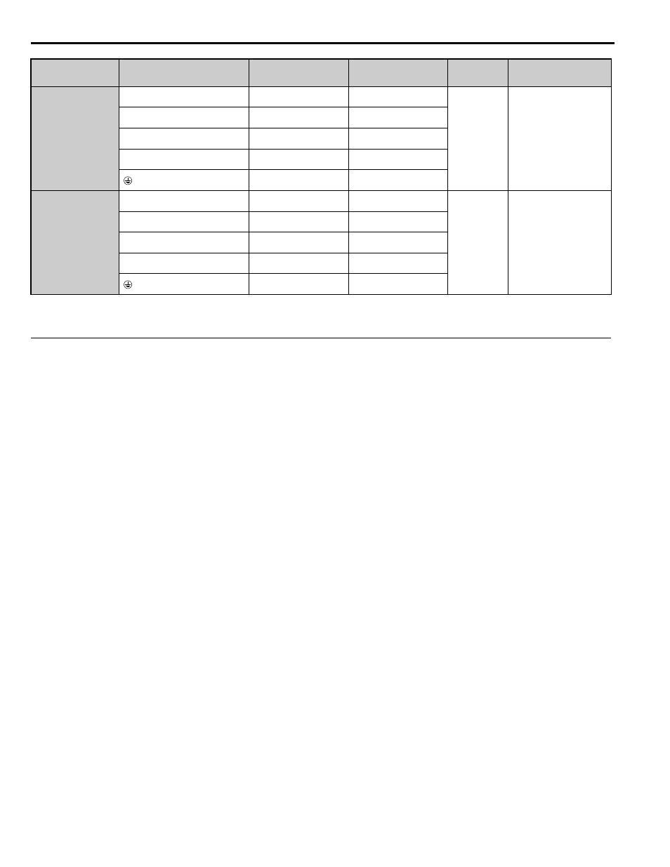
4A0260
R/L1, S/L2, T/L3
70
× 2P
(2/0
× 2P)
95 to 300
(1 to 600)
M10
18 to 23
(159 to 204)
U/T1, V/T2, W/T3
70
× 2P
(2/0
× 2P)
95 to 300
(1/0 to 600)
–, +1
–
70 to 300
(3/0 to 600)
+3
–
35 to 185
(1 to 325)
35
(2)
35 to 185
(2 to 350)
Drive Model
Terminal
Recommended
Wire Size
mm
2
(AWG, kcmil)
Wire Range
mm
2
(AWG, kcmil)
Screw
Size
Tightening Torque
N•m (lb.in.)