N8: pm motor control tuning, Position search is finished, Refer to n8-35: initial rotor – Yaskawa L1000E AC Drive Technical Manual for CIMR-LE Models for Elevator Applications User Manual
Page 236: For details on motor, N6-05: online tuning gain, Initial rotor pole position search settings, N8-01: initial polarity estimation current, N8-02: pole attraction current, N8-35: initial rotor position detection selection, 9 n: special adjustments
5.9 n: Special Adjustments
236
YASKAWA ELECTRIC SIEP YAIL1E 01A YASKAWA AC Drive L1000E Technical Manual
Setting 2: Voltage correction
The drive adjusts the output voltage during run to improve overload tolerance and minimize the effects of high
temperatures on speed accuracy.
Note: This setting can only be selected if the Energy Saving function is disabled (b8-01 = 0).
■
n6-05: Online Tuning Gain
Sets the compensation gain for the voltage correction in the Online Tuning function (n6-01 = 2). Although this parameter
rarely needs to be changed, increase the set value in steps of 0.1 if an overload fault occurs during voltage correction.
◆ n8: PM Motor Control Tuning
Parameters in the n8 group are used to adjust the Initial Rotor Pole Position Search function and other PM motor control
related functions like the current control loop in CLV/PM or voltage saturation prevention (voltage limit).
■
Initial Rotor Pole Position Search Settings
When a PM motor with a non-absolute encoder such as an incremental encoder with a PG-X3 option is used, the drive
needs to search for the rotor pole position before it can operate the motor. This search is performed always:
• when the Up/Down command is issued for the first time after the power has been switched on.
• after one of the following errors occurred: dv1, dv2, dv3, dv4, dv6, dv7, PGo, PGoH.
• when an Up/Down command issued after the setting of parameter n8-35 had been changed.
With default settings the drive will generate a dv8 error if initial rotor pole position search fails (n8-86 = 1). The brake
control output (H2- = 50) will not open in this case.
When not using the drive’s brake sequence, include the Motor Pole Search Status signal (digital output programmed for
H2- = 61) so that the brake can open only if motor pole position search has been finished successfully.
Setting 61: Motor pole search status on page 207
for details.
■
n8-01: Initial Polarity Estimation Current
Sets the current used for the initial rotor position estimation as a percentage of the motor rated current.
■
n8-02: Pole Attraction Current
Sets the pull-in current used to detect rotor position. This setting rarely needs to be changed.
■
n8-35: Initial Rotor Position Detection Selection
Selects how the rotor position is detected at start.
Setting 1: High Frequency Injection
High frequency is injected in order to detect the rotor position. Some noise may be generated from the motor at start.
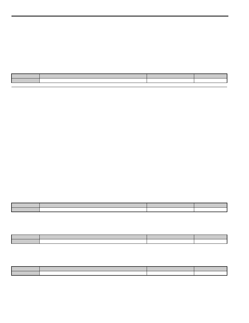
No.
Parameter Name
Setting Range
Default
n6-05
Online Tuning Gain
0.1 to 50.0
1.0
No.
Parameter Name
Setting Range
Default
n8-01
Initial Polarity Estimation Current
0 to 100%
50%
No.
Parameter Name
Setting Range
Default
n8-02
Pole Attraction Current
0 to 150%
80%
No.
Parameter Name
Setting Range
Default
n8-35
Initial Rotor Position Detection Selection
1 or 2
1