Table 5.12, Common tmonly, 7 h: terminal functions – Yaskawa L1000E AC Drive Technical Manual for CIMR-LE Models for Elevator Applications User Manual
Page 198: Setting 1: zero speed, Figure 5.18 zero-speed time chart
5.7 H: Terminal Functions
198
YASKAWA ELECTRIC SIEP YAIL1E 01A YASKAWA AC Drive L1000E Technical Manual
Table 5.12 Multi-Function Digital Output Terminal Settings
Setting 0: During Run
Output closes when the drive is outputting a voltage.
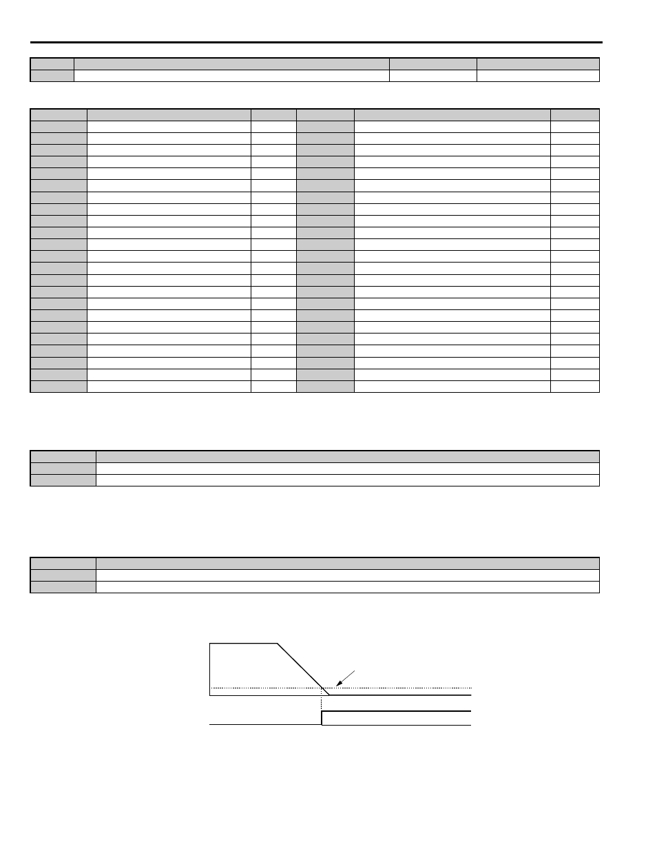
Setting 1: Zero Speed
Terminal closes whenever the output speed or motor speed (CLV, CLV/PM) becomes less than the minimum output speed
set to E1-09 or S1-01.
Note: When using CLV or CLV/PM control modes, the output terminal will close when the motor speed becomes less than or equal to
the zero speed level set for S1-01. In all other control modes, the output terminal will close when the output frequency becomes
less than or equal to the minimum output frequency set for E1-09.
Figure 5.18
Figure 5.18 Zero-Speed Time Chart
H2-05
Terminals P2-C2 Function Selection (photocoupler)
0 to 161
F: Through Mode
Setting
Function
Page
Setting
Function
Page
0
During Run
1B
During Baseblock 2 (N.C.)
1
Zero Speed
1C
Motor 2 Selection
2
Speed Agree 1
1D
During Regeneration
3
User-set Speed Agree 1
1E
Restart Enabled
4
Speed Detection 1
1F
Motor Overload Alarm (oL1)
5
Speed Detection 2
20
Drive Overheat Pre-alarm (oH)
6
Drive Ready (READY)
2F
Maintenance Period
7
DC Bus Undervoltage
30
During Torque Limit
8
During Baseblock (N.O.)
33
Within Position Lock Bandwidth
9
Speed Reference Source
37
During Frequency Output
A
Up/Down Command Source
50
Brake Control
B
Torque Detection 1
47
Input Phase Loss
E
Fault
4E
Braking Transistor Fault (rr)
F
Not used (Through Mode)
51
Output Contactor Control
10
Minor Fault
52
Door Zone Reached
11
Fault Reset Command Active
53
Not Zero Speed
12
Timer Output
54
Light Load Direction
13
Speed Agree 2
55
Light Load Direction Detection Status
14
User-set Speed Agree 2
58
Safe Disable Status
15
Speed Detection 3
5C
Motor Current Monitor
16
Speed Detection 4
60
Internal Cooling Fan Alarm
18
Torque Detection 2
61
Motor Pole Search Status
1A
During Reverse
100 to 161
Functions 0 to 61 with Inverse Output
Status
Description
Open
Drive is stopped.
Closed
An Up/Down command is input or the drive is during deceleration or during DC injection.
Status
Description
Open
The operating speed is greater than the minimum output frequency (E1-09) or the zero speed level at stop (S1-01).
Closed
The operating speed is less than or equal to the minimum output frequency (E1-09) or the zero speed level at stop (S1-01).
No.
Parameter Name
Setting Range
Default
OFF
Output speed
or
motor speed
Zero Speed
ON
E1-09 (Max. Output Frequency) or
S1-01 (Zero Speed Level)
common
TMonly