Flowchart c: auto-tuning for pm motors, Yea_comm, 4 start-up flowcharts – Yaskawa L1000E AC Drive Technical Manual for CIMR-LE Models for Elevator Applications User Manual
Page 107
4.4 Start-Up Flowcharts
YASKAWA ELECTRIC SIEP YAIL1E 01A YASKAWA AC Drive L1000E Technical Manual
107
St
ar
t-
U
p
Pr
og
ra
m
m
in
g
&
Op
er
at
io
n
4
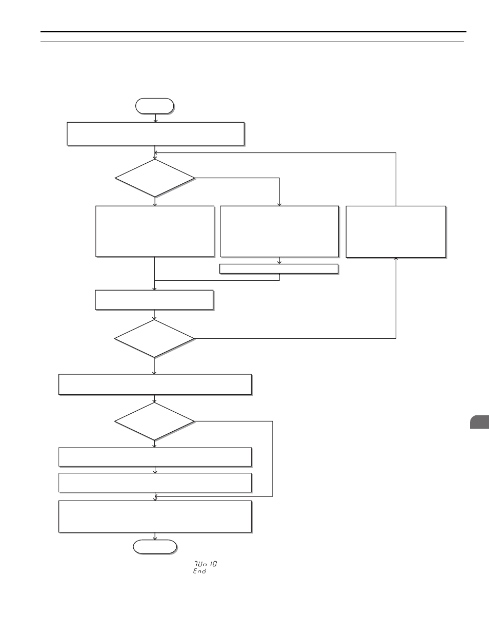
◆ Flowchart C: Auto-Tuning for PM Motors
The flowchart below covers Auto-Tuning for permanent magnetic (PM) motors operating with Closed Loop Vector
Control for PM motors.
Figure 4.14 Auto-Tuning for PM Motors
<1> If an LED operator is used, the display shows “
”.
<2> If an LED operator is used, the display shows “
”.
Can the motor
rotate freely?
START
Set terminals H1-HC and H2-HC if Safe Disable function is used.
Is the motor data
sheet available?
FINISH
No
Yes
Select Stationary Auto-Tuning
T2-01 = 1.
Continue with encoder offset tuning.
Press the Run key on the digital operator
and wait until Auto-Tuning is finished.
Set the Baseblock input (H1-
= 8/9) if used.
Tuning
Successful?
Refer to
Remove the Fault/Alarm source and
repeat Auto Tuning.
Open terminals H1-HC and H2-HC if used during the normal sequence.
Open the motor contactor(s).
Open the Baseblock input (H1-
= 8/9) if used.
No
(Alarm or Fault code
displayed
Yes
(“Entry Accepted”
displayed
<2>
Enter the data in to T2-
parameters as
indicated on the display.
Select Motor Data Input
T2-01 = 0.
Enter the data in to T2-
parameters as
indicated on the display.
Press the Up key until “Tuning Ready” is
displayed.
<1>
Press the Up key until “Tuning Ready” is
displayed.
<1>
Close the motor contactor.
No
(Alarm or Fault code
displayed
・ Select Rotational Back EMF Constant Auto-Tuning T2-01=11.
・ Press the Up key.
Press the Run key on the digital operator
and wait until Auto-Tuning is finished.
Yes (Ropes removed)
No
Refer to
Flowchart D: PG Encoder Offset Auto-Tuning on page 108
.
YEA_comm