Motor switch selection, D1-27: motor 2 speed reference, D1-28: leveling speed detection level – Yaskawa L1000E AC Drive Technical Manual for CIMR-LE Models for Elevator Applications User Manual
Page 176: D1-29: inspection speed detection level, 4 d: reference settings, Sets the speed reference for motor 2

5.4 d: Reference Settings
176
YASKAWA ELECTRIC SIEP YAIL1E 01A YASKAWA AC Drive L1000E Technical Manual
■
Motor Switch Selection
When an input terminal selects motor 2 (H1-= 16), the drive will operate a second motor using V/f Control. The drive
cannot control motor 2 with OLV, CLV or CLV/PM.
The motor 2 speed reference in d1-27 can also be used to operate motor 1 using V/f Control. Refer to
for
combinations of selecting the speed reference for motor 2 and the motor 1/2 selection switch. (H1- = 53).
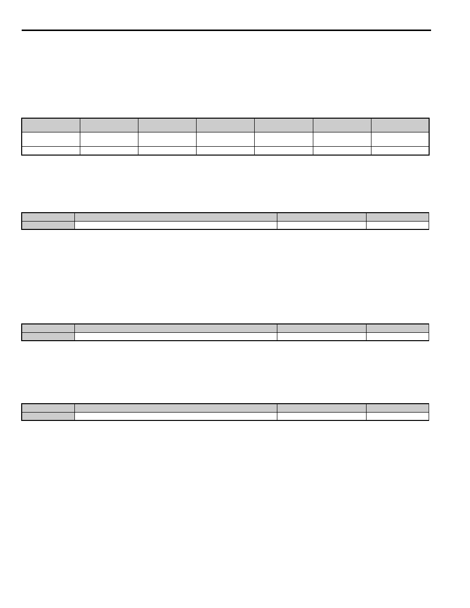
Table 5.8 Speed Reference for Motor 2, Controlling Motor 1 and 2
■
d1-27: Motor 2 Speed Reference
Sets the speed reference for motor 2.
Note: 1. The drive will control motor 1 when this parameter is set to 0.00.
2. Set the accel/decel times in parameters C1-12 and C1-13 when using motor 2.
3. When motor 2 is selected, the following monitors will display values in Hz: U1-01, U1-02, U1-05, U4-19, U4-20.
■
d1-28: Leveling Speed Detection Level
When the speed priority selection in d1-18 is set to “0” or “3” and the speed reference value falls below the level set in d1-
28, the drive interprets the selected speed as leveling speed. This parameter must be set to use the Speed Control Loop
setting 3 when d1-18 = 0/3.
Refer to C5: Speed Control Loop on page 169
for details.
■
d1-29: Inspection Speed Detection Level
When the speed priority selection in d1-18 is set to “0” or “3” and the speed reference value is below the level set in d1-
29 but higher than the level set in d1-28, the drive interprets the selected speed as inspection speed. This parameter must
be set to use the Inspection Operation function when d1-18 = 0/3.
Refer to Inspection Operation on page 124
for details.
The value set to d1-27
<1> Enter the same values to the E3 and E4 parameters that are set for the E1 and E2 parameters.
Speed reference
Control mode
Accel/Decel ramp
S-character/ Jerk
Contactor/
Brake sequence
Purpose
0.00
speed reference set to
Motor 1
C1-01 to C1-08
C2-01 to C2-05
Available
Hoist
not 0.00
d1-27
V/f with motor 2
C1-12/C1-13
N.A.
N.A.
Not for hoist
No.
Parameter Name
Setting Range
Default
d1-27
Motor 2 Speed Reference
0.00 to 120.00 Hz
0.00 Hz
No.
Parameter Name
Setting Range
Default
d1-28
Leveling Speed Detection Level
0.0 to 100.0%
0.0%
No.
Parameter Name
Setting Range
Default
d1-29
Inspection Speed Detection Level
0.0 to 100.0%
0.0%
