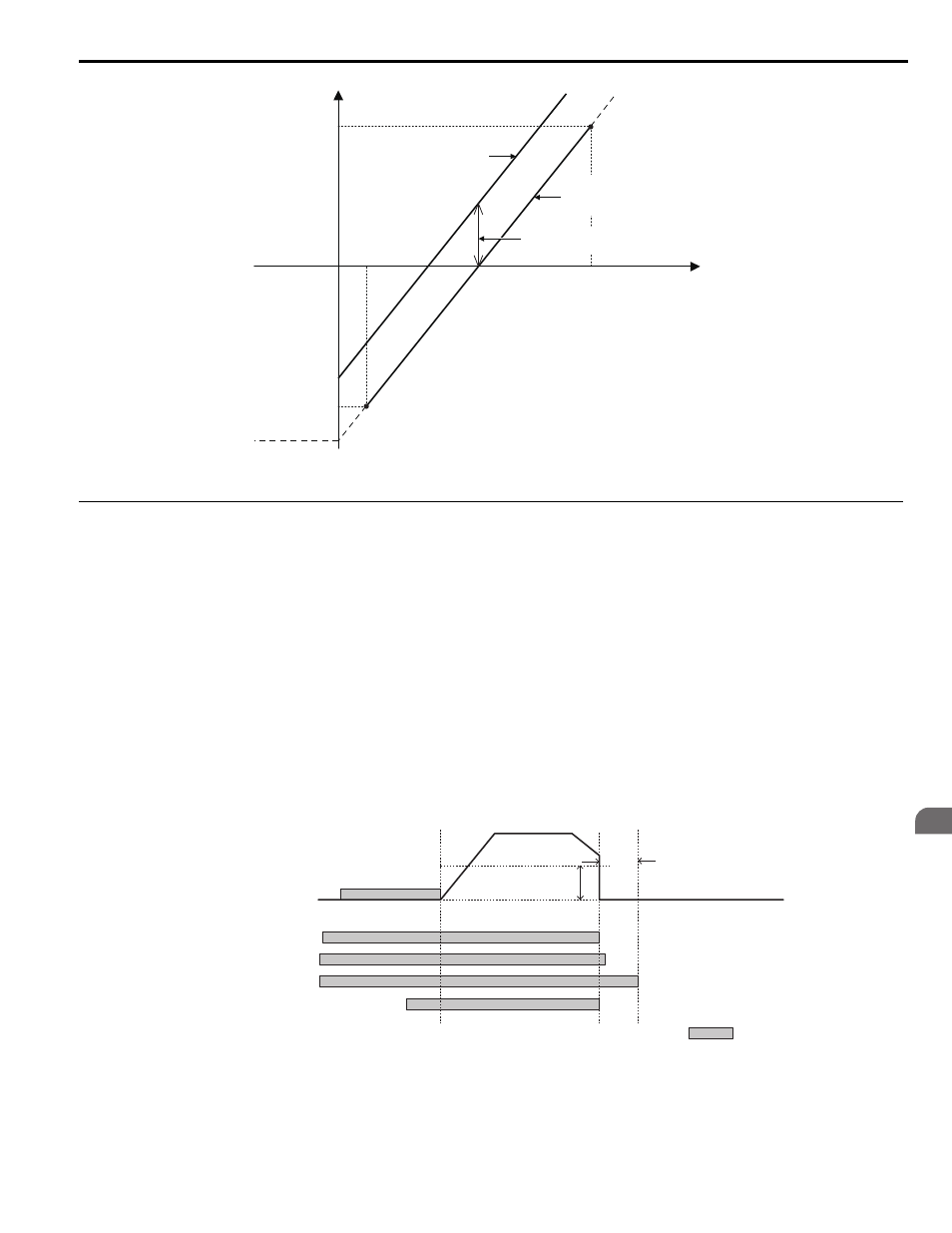
Elevator emergency stop, Figure 4.22, Elevator emergency stop timing chart – Yaskawa L1000E AC Drive Technical Manual for CIMR-LE Models for Elevator Applications User Manual
Page 129: 6 setup procedure for elevator applications

4.6 Setup Procedure for Elevator Applications
YASKAWA ELECTRIC SIEP YAIL1E 01A YASKAWA AC Drive L1000E Technical Manual
129
St
ar
t-
U
p
Pr
og
ra
m
m
in
g
&
Op
er
at
io
n
4
Figure 4.17
Figure 4.22 Torque Compensation at Start for the Elevator in Up and Down Direction
◆ Elevator Emergency Stop
■
Start Condition for Elevator Emergency Coast to Stop
An emergency coast to stop is performed when the Up or Down command is cleared and all of the following conditions
are met.
• Parameter b1-03 (Stopping Method Selection) is set to 4.
• Parameter d1-18 (Speed Reference Selection Mode) is set to 0 or 3.
• Parameter b1-01 (Speed Reference Selection) is set to 1.
• The Up/Down command is cleared and U1-05 (Speed Feedback) is equal to or greater than S1-26 (Emergency Stop
Start Level).
■
Elevator Emergency Stop Timing Chart
show timing charts for Elevator Emergency Coast to Stop and normal Ramp to Stop.
Figure 4.18
Figure 4.23 With Up/Down Command Cleared and U1-05
≥ S1-26
S3-30
S3-27
S3-28
(Torque Compensation
Value with Load Condition 2)
Torque Compensation
at Start for the Elevator
in Down Direction
S3-29
(Analog Input
from Load Sensor
with Load
Condition 1)
(Torque Compensation Value
with Load Condition 1)
During Load Condition 2
Torque Compensation
at Start for the Elevator
in Up Direction
S3-12 (Starting Torque
Compensation Bias during Lowering)
(Analog input
from Load Sensor
with Load Condition 2)
Analog Input Voltage (V)
During Load Condition 1
0
Speed
Selected Speed
S1-11
(Output Contactor Open
Delay Time)
S1-26
Emergency Stop
Start Level
DC Injection Braking/
Position Lock at Start
Coast to Stop
Up/Down Command
Safe disable (terminals H1/H2 on)
or Baseblock off (H1-
= 8/9)
H2-
= 51 (Output Cont. Contr.)
H2-
= 50 (Brake Control)
Enabled
