Terminal configuration, Serial communication terminals, Wire size and torque specifications – Yaskawa L1000E AC Drive Technical Manual for CIMR-LE Models for Elevator Applications User Manual
Page 75: Yea_common, 8 control circuit wiring, Table 3.8 wire gauges and torque specifications
3.8 Control Circuit Wiring
YASKAWA ELECTRIC SIEP YAIL1E 01A YASKAWA AC Drive L1000E Technical Manual
75
El
ec
tr
ic
al
In
st
al
la
ti
o
n
3
■
Serial Communication Terminals
Table 3.7 Control Circuit Terminals: Serial Communications
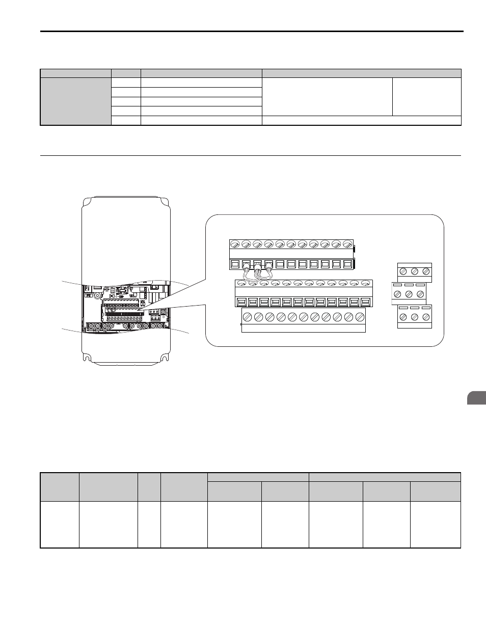
◆ Terminal Configuration
Control circuit terminals are arranged as shown in
.
Figure 3.18
Figure 3.19 Control Circuit Terminal Arrangement
■
Wire Size and Torque Specifications
WARNING! Fire hazard. Tighten all terminal screws to the specified tightening torque. Loose electrical connections could result in
death or serious injury by fire due to overheating of electrical connections. Improperly tightened terminal screws can also cause
erroneous equipment operation.
Select appropriate wire type and gauges from
. For simpler and more reliable wiring, use crimp ferrules on the
wire ends. Refer to
for ferrule terminal types and sizes.
Table 3.8 Wire Gauges and Torque Specifications
Type
<1> Enable the termination resistor in the last drive in a MEMOBUS network by setting DIP switch S2 to the ON position. For more information on
Refer to Control I/O Configuration on page 79
No.
Signal Name
Function (Signal Level)
MEMOBUS/Modbus
Communication
R+
Communications input (+)
MEMOBUS/Modbus communication: Use an RS-485 or
RS-422 cable to connect the drive.
RS-485/422
MEMOBUS/Modbus
communication protocol
115.2 kbps (max.)
R-
Communications input (-)
S+
Communications output (+)
S-
Communications output (-)
IG
Shield ground
0 V
Terminal
Block
Terminal
Size
Tightening
Torque
N"m
(lb.in.)
Bare Wire Terminal
Ferrule-Type Terminal
Applicable Wire
Size
mm
2
(AWG)
Recomm. mm
2
(AWG)
Applicable Wire
Size
mm
2
(AWG)
Recomm. mm
2
(AWG)
Wire Type
TB1, TB2,
TB4, TB5,
TB6
FM, AC, AM, P1, P2,
PC, SC, A1, A2, A3,
+V, -V, S1-S8, MA,
MB, MC, M1, M2, HC,
H1, H2, DM+, DM-, IG,
R+, R-, S+, S-, RP, MP,
E (G)
M2
0.22 to 0.25
(1.9 to 2.2)
Standard wire:
0.25 to 1.0
(24 to 17)
Solid wire:
0.25 to 1.5
(24 to 16)
0.75
(18)
0.25 to 0.5
(24 to 20)
0.5
(20)
Shielded wire, etc.
E(G) HC H1
H2 DM+ DM- IG
R+
R-
S+
S-
S1
S2
S3
S4
S5
S6
S7
S8
SN SC SP
V+ AC
V-
A1
A2 FM AM AC
P1
C1
C2
P2
M3 M4
M6
MA MB MC
M1 M2 M5
YEA_common