Analog input functions, Refer to multi, Table 5.13 – Yaskawa L1000E AC Drive Technical Manual for CIMR-LE Models for Elevator Applications User Manual
Page 209: A1. refer to, H3-10: terminal a2 function selection, H3-13: analog input filter time constant, Multi-function analog input terminal settings, 7 h: terminal functions
5.7 H: Terminal Functions
YASKAWA ELECTRIC SIEP YAIL1E 01A YASKAWA AC Drive L1000E Technical Manual
209
P
a
ra
me
te
r De
ta
ils
5
Setting 1: –10 to 10 Vdc
The input level is –10 to 10 Vdc. Refer to
Setting 1: –10 to 10 Vdc on page 207
■
H3-10: Terminal A2 Function Selection
Determines the function assigned to analog input terminal A2. Refer to
Multi-Function Analog Input Terminal Settings
for a list of functions and descriptions.
■
H3-11, H3-12: Terminal A2 Gain and Bias Setting
Parameter H3-11 sets the level of the input value selected that is equal to 10 Vdc input to terminal A2.
Parameter H3-12 sets the level of the input value selected that is equal to 0 V at terminal A2.
Both can be used to adjust the characteristics of the analog input signal to terminal A2. The settings work in the same way
as parameters H3-03 and H3-04 for analog input A1.
■
H3-13: Analog Input Filter Time Constant
Parameter H3-13 sets the time constant for a first order filter that will be applied to the analog inputs.
An analog input filter prevents erratic drive control when using a “noisy” analog reference. Drive operation becomes
more stable as the programmed time becomes longer, but it also becomes less responsive to rapidly changing analog
signals.
■
H3-16/H3-17: Offset for Terminal A1/A2
Parameters H3-16 and H3-17 set the offset applied analog input values from terminals A1 and A2.
Although adjustment is rarely required, these parameters can be used for zero adjustment of the analog inputs.
■
Multi-Function Analog Input Terminal Settings
Refer to
for information on how H3-02 and H3-10 determine functions for terminals A1 and A2.
Note: The scaling of all input functions depends on the gain and bias settings for the analog inputs. Set these to appropriate values when
selecting and adjusting analog input functions.
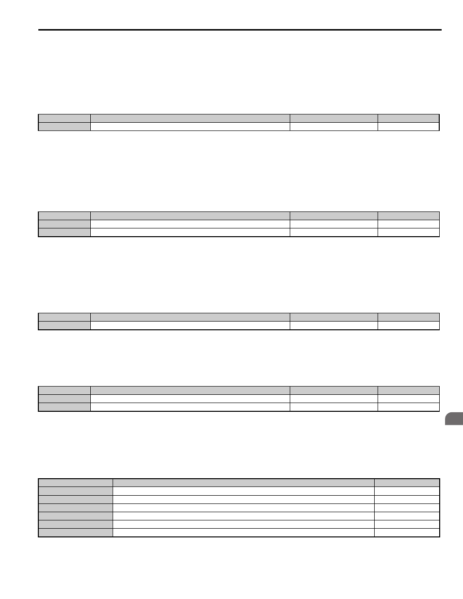
Table 5.13 Multi-Function Analog Input Terminal Settings
No.
Parameter Name
Setting Range
Default
H3-10
Terminal A2 Function Selection
0 to 1F
1F
No.
Parameter Name
Setting Range
Default
H3-11
Terminal A2 Gain Setting
-999.9 to 999.9%
100.0%
H3-12
Terminal A2 Bias Setting
-999.9 to 999.9%
0.0%
No.
Parameter Name
Setting Range
Default
H3-13
Analog Input Filter Time Constant
0.00 to 2.00 s
0.03 s
No.
Parameter Name
Setting Range
Default
H3-16
Offset for Terminal A1
–500 to 500
0
H3-17
Offset for Terminal A2
–500 to 500
0
Setting
Function
Page
0
Speed reference bias
2
Auxiliary speed reference 1 (used as a second speed reference)
3
Auxiliary speed reference 2 (used as a third speed reference)
E
Motor Temperature (PTC thermistor input)
14
Torque compensation (load cell input)
1F
Not used (through mode)