Common_tmo, 7 h: terminal functions, Terminal am 1 – Yaskawa L1000E AC Drive Technical Manual for CIMR-LE Models for Elevator Applications User Manual
Page 211
5.7 H: Terminal Functions
YASKAWA ELECTRIC SIEP YAIL1E 01A YASKAWA AC Drive L1000E Technical Manual
211
P
a
ra
me
te
r De
ta
ils
5
■
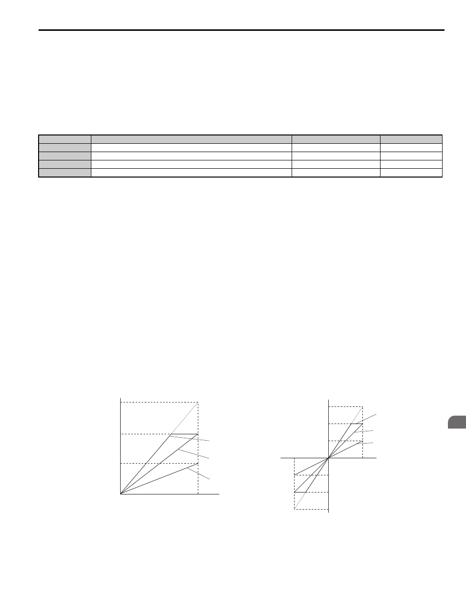
H4-02, H4-03: Multi-Function Analog Output Terminal FM Gain and Bias
H4-05, H4-06: Terminal AM Gain and Bias
Parameters H4-02 and H4-05 set the terminal FM and AM output signal level equal to 100% of the monitor (gain).
Parameters H4-03 and H4-06 set the bias added to the monitor output for terminals FM and AM. Both are set as a
percentage, where 100% equals 10 Vdc analog output. The output voltage of both terminals is limited to 10 Vdc.
Select an output signal range between 0 to +10 Vdc or -10 to +10 Vdc using parameters H4-07 and H4-08.
illustrates how gain and bias settings work.
Using Gain and Bias to Adjust Output Signal Level
The output signal is adjustable while the drive is stopped.
Terminal FM
1.
View the value set to H4-02 (Terminal FM Monitor Gain) on the digital operator. A voltage equal to 100% of the
parameter being set in H4-01 will be output from terminal FM.
2.
Adjust H4-02 viewing the monitor connected to the terminal FM.
3.
View the value set to H4-03 on the digital operator, terminal FM will output a voltage equal to 0% of the parameter
being set in H4-01.
4.
Adjust H4-03 viewing the output signal on the terminal FM.
Terminal AM
1.
View the value set to H4-05 (Terminal AM Monitor Gain) on the digital operator. A voltage equal to 100% of the
parameter being set in H4-04 will be output from terminal AM.
2.
Adjust H4-05 viewing the monitor connected to the terminal AM.
3.
View the value set to H4-06 on the digital operator, terminal AM will output a voltage equal to 0% of the parameter
being set in H4-04.
4.
Adjust H4-06 viewing the output signal on the terminal AM.
Example 1: Set H4-02 to 50% for an output signal of 5 V at terminal FM when the monitored value is at 100%.
Example 2: Set H4-02 to 150% for an output signal of 10 V at terminal FM when the monitored value is at 76.7%.
Figure 5.31
Figure 5.31 Analog Output Gain and Bias Setting Example 1 and 2
No.
Parameter Name
Setting Range
Default
H4-02
Terminal FM Gain
-999.9 to 999.9%
100.0%
H4-03
Terminal FM Bias
-999.9 to 999.9%
0.0%
H4-05
Terminal AM Gain
-999.9 to 999.9%
50.0%
H4-06
Terminal AM Bias
-999.9 to 999.9%
0.0%
Output Voltage
Output Voltage
0 V
5 V
10 V
Gain 150%
Bias 0%
Gain = 150%
Bias = 0%
Gain = 100%
Bias = 0%
Gain = 50%
Bias = 0%
Gain 100%
Bias 0%
Gain 50%
Bias 0%
100%
Monitor Value
Monitor Value
0%
H4-07, 08 = 0
H4-07, 08 = 1
10
V
-10 V
100%
5 V
15
V
-5 V
-15 V
-100%
common_TMo