Grounding, Guarding against harmful materials, Low voltage wiring for control circuit terminals – Yaskawa L1000E AC Drive Technical Manual for CIMR-LE Models for Elevator Applications User Manual
Page 455: Drive short circuit rating, D.2 ul standards, Table d.5 control circuit terminal power supply
D.2 UL Standards
YASKAWA ELECTRIC SIEP YAIL1E 01A YASKAWA AC Drive L1000E Technical Manual
455
St
an
dar
d
s
Complianc
e
D
■
Grounding
The drive is designed to be used in T-N (grounded neutral point) networks. If installing the drive in other types of
grounded systems, contact your Yaskawa representative for instructions.
■
Guarding Against Harmful Materials
When installing IP00 enclosure drives, use an enclosure that prevents foreign material from entering the drive from above
or below.
■
Low Voltage Wiring for Control Circuit Terminals
Wire low voltage wires with NEC Class 1 circuit conductors. Refer to national state or local codes for wiring. If external
power supply used, it shall be UL Listed Class 2 power source only or equivalent. Refer to NEC Article 725 Class 1,
Class 2, and Class 3 Remote-Control, Signaling, and Power Limited Circuits for requirements concerning class 1 circuit
conductors and class 2 power supplies.
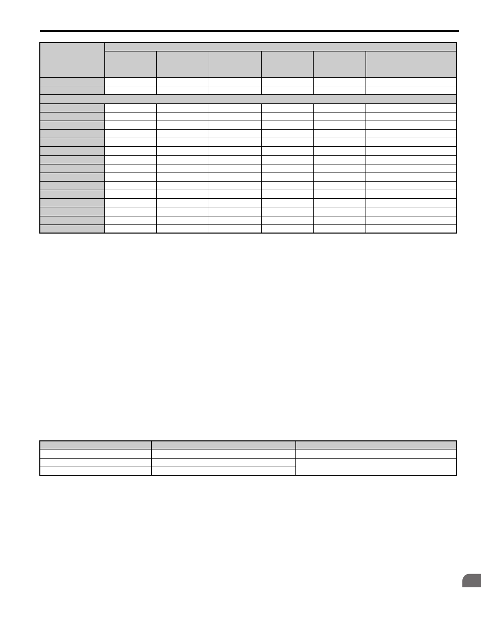
Table D.5 Control Circuit Terminal Power Supply
■
Drive Short Circuit Rating
This drive is suitable for use on a circuit capable of delivering not more than 100,000 RMS symmetrical amperes,
480 Vac maximum (Up to 240 V in 200 V class drives, up to 480 V for 400 V class drives), when protected by fuses or
circuit breakers as specified in
2A0354
125
271
500
450
800
FWH-700A (700)
2A0432
150
324
600
500
FWH-800A (800)
480 V Models
4A0009
5
8.2
15
12
20
FWH-90B (90)
4A0012
7.5
10.4
20
17.5
30
FWH-90B (90)
4A0019
10
15
30
25
40
FWH-80B (80)
4A0023
15
20
40
35
60
FWH-100B (100)
4A0030
20
29
50
50
80
FWH-125B (125)
4A0039
25
39
75
60
110
FWH-200B (200)
4A0049
30
44
75
75
125
FWH-250A (250)
4A0056
40
43
75
75
125
FWH-250A (250)
4A0075
50
58
100
100
150
FWH-250A (250)
4A0094
60
71
125
110
200
FWH-250A (250)
4A0114
75
86
150
150
250
FWH-250A (250)
4A0140
100
105
175
175
300
FWH-350A (350)
4A0188
125
142
225
225
400
FWH-400A (400)
4A0225
150
170
250
250
500
FWH-500A (500)
4A0260
175
207
350
350
600
FWH-600A (600)
<1> Maximum MCCB Rating is 15 A, or 200% of drive input current rating, whichever is larger. MCCB voltage rating must be 600 Vac or greater.
<2> Maximum Time Delay fuse is 175% of drive input current rating. This covers any Class CC, J or T class fuse.
<3> Maximum Non-time Delay fuse is 300% of drive input current rating. This covers any CC, J or T class fuse.
<4> When using semiconductor fuses, Bussmann FWH is required for UL compliance.
<5> Class L fuse is also approved for this rating.
Input / Output
Terminal Signal
Power Supply Specifications
Open Collector Outputs
P1, C1, P2, C2, DM+, DM-
Requires class 2 power supply
Digital inputs
S1-S8, SN, SC, SP, HC, H1, H2
Use the internal LVLC power supply of the drive. Use class 2 for
external power supply.
Analog inputs / outputs
+V, -V, A1, A2, AC, AM, FM
Drive Model
CIMR-LE
L1000E
Nominal Output
Power HP
AC Drive Input
Amps
MCCB Rating
Amps
<1>
Time Delay Fuse
Rating Amps
<2>
Non-time Delay
Fuse Rating Amps
<3>
Bussmann
Semi-conductor Fuse Rating
(Fuse Ampere)
<4>