F1-20: pg option card disconnect detection 1, F1-29: dev detection condition selection, F1-50: encoder selection – Yaskawa L1000E AC Drive Technical Manual for CIMR-LE Models for Elevator Applications User Manual
Page 188: F1-51: pgoh detection level, Commo n, 6 f: option settings, Selects when dev error detection is active, Θ + cos, Θ = 1
5.6 F: Option Settings
188
YASKAWA ELECTRIC SIEP YAIL1E 01A YASKAWA AC Drive L1000E Technical Manual
■
F1-20: PG Option Card Disconnect Detection 1
Sets whether the drive detects a fault when a speed feedback card is disconnected.
Setting 0: Disabled
Setting 1: Enabled
■
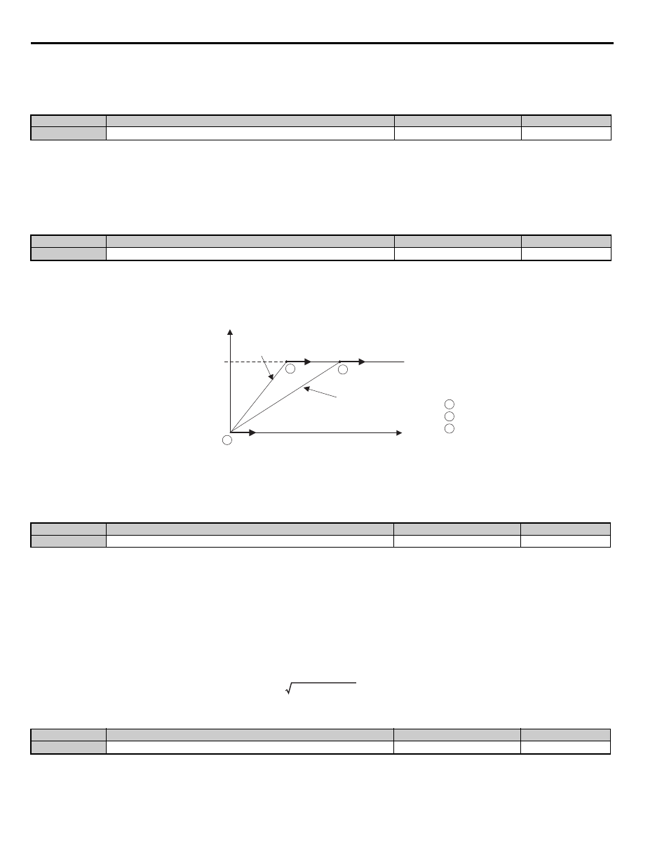
F1-29: dEv Detection Condition Selection
Selects when dEv error detection is active.
Setting 0: After speed reference, SFS output and motor speed have matched once.
Setting 1: After speed reference, SFS output have matched once.
Setting 2: Always during Run.
Figure 5.15
Figure 5.15 Speed Deviation Detection Conditions Flowchart
■
F1-50: Encoder Selection
Sets up the type of encoder connected to a PG-F3 option card.
Setting 0: EnDat 2.1/01, 2.2/01 Serial Communications operation + Sin/Cos
Setting 1: EnDat 2.2/22 Serial Communications operation
Setting 2: Hiperface
The use of EnDat2.2/22 encoders requires a PG-F3 option with software version 0102 or later.
To identify the PG-F3 software version refer to the PG-F3 labeling in the field designated “C/N” (S + four digit number).”
■
F1-51: PGoH Detection Level
Sets the level for detecting PG Hardware Fault (PGoH).
Usually the relation between the sin and cos track is
. If the value of the square root falls below the
level set in F1-51, a speed feedback hardware fault is detected. Available when F1-20 = 1.
No.
Parameter Name
Setting Range
Default
F1-20
PG Option Card Disconnect Detect 1
0 or 1
1
No.
Parameter Name
Setting Range
Default
F1-29
dEv Detection Condition Selection
0 to 2
2
No.
Parameter Name
Setting Range
Default
F1-50
Encoder Selection
0 to 2
0
No.
Parameter Name
Setting Range
Default
F1-51
PGoH Detection Level
1 to 100%
80%
Speed reference
Speed
Soft Starter Output and Calculating
the Speed Reference
Motor speed
: Setting 2
: Setting 1
: Setting 0
C
B
A
A
B
C
Time
commo
n_
sin
2
θ + cos
2
θ = 1