Network termination, Network termination on, Figure c.4 – Yaskawa L1000E AC Drive Technical Manual for CIMR-LE Models for Elevator Applications User Manual
Page 421: Rs-422 interface, C o m - mon_ tmonly, Yea_t m only, C.3 connecting to a network
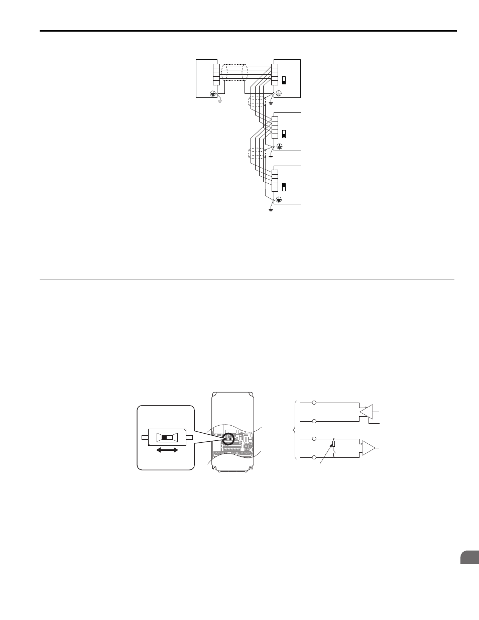
C.3 Connecting to a Network
YASKAWA ELECTRIC SIEP YAIL1E 01A YASKAWA AC Drive L1000E Technical Manual
421
MEMOBUS
/Mo
dbu
s
C
o
m
m
u
ni
ca
ti
on
s
C
■
RS-422 Interface
Figure C.4
Figure C.4 RS-422 Interface
Note: 1. Turn on the DIP switch on the drive that is located at the end of the network. All other slave devices must have this DIP switch set to
the OFF position.
2. Set H5-07 to 0 when using the RS-485 interface.
Set H5-07 to 1 when using the RS-422 interface in multi-drop circuit. Set H5-07 to 0 when using the RS-422 interface in point-to-
point circuit.
◆ Network Termination
The two ends of the MEMOBUS/Modbus network line have to be terminated. The drive has a built in termination resistor
that can be enabled or disabled using DIP switch S2. If a drive is located at the end of a network line, enable the
termination resistor by setting DIP switch S2 to the ON position. Disable the termination resistor on all slaves that are not
located at the network line end.
illustrates the setting of DIP switch S2.
To set the DIP switch on the terminal board, use an appropriate sized tool with a tip of approximately 8 mm (5/16 in.) in
width.
Figure C.5
Figure C.5 Serial Communications Terminal and DIP Switch S2
R–
R+
S–
S+
IG
PLC
Drive
Drive
Drive
S–
S+
R–
R+
IG
S–
S+
R–
R+
IG
S–
S+
R–
R+
IG
S2
OFF
S2
OFF
S2
ON
c o m -
mon_
TMonly
RS-422
or
RS-485
R-
R+
DIP
switch
S2
S-
S+
+
-
Termination resistor (1/2 W
, 110
Ω)
DIP Switch S2
(OFF: default)
OFF
ON
YEA_T
M
only