B.5 defaults by drive model selection (o2-04) – Yaskawa L1000E AC Drive Technical Manual for CIMR-LE Models for Elevator Applications User Manual
Page 415
B.5 Defaults by Drive Model Selection (o2-04)
YASKAWA ELECTRIC SIEP YAIL1E 01A YASKAWA AC Drive L1000E Technical Manual
415
Pa
ra
met
er
L
is
t
B
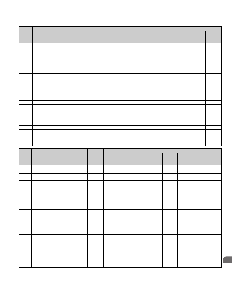
Table B.5 400 V Class Drives Default Settings by Drive Capacity
No.
Name
Unit
Default Settings
–
Model CIMR-LE
–
4A0009
4A0012
4A0019
4A0023
4A0030
4A0039
4A0049
o2-04
Drive Model Selection
Hex.
96
97
99
9A
9C
9D
9E
E2-11
Motor Rated Output
HP
5
7.5
10
15
20
25
30
C5-17
Motor Inertia
kgm
2
0.0158
0.0158
0.026
0.037
0.053
0.076
0.138
C6-03
Carrier Frequency
kHz
8
8
8
8
8
8
8
E2-01 (E4-
01)
Motor Rated Current
A
5.7
7
9.8
13.3
19.9
26.5
32.9
E2-02 (E4-
02)
Motor Rated Slip
Hz
2.7
2.7
1.5
1.3
1.7
1.6
1.67
E2-03 (E4-
03)
Motor No-Load Current
A
1.9
2.3
2.6
4
5.6
7.6
7.8
E2-05 (E4-
05)
Motor Line-to-Line Resistance
Ω
4.36
3.333
1.595
1.152
0.922
0.55
0.403
E2-06 (E4-
06)
Motor Leakage Inductance
%
19
19.3
18.2
15.5
19.6
17.2
20.1
E2-10
Motor Iron Loss for Torque Compensation
W
105
130
193
263
385
440
508
E3-08
Motor 2 Mid Output Frequency Voltage
V
32.2
32.2
32.2
32.2
32.2
32.2
32.2
E3-10
Motor 2 Minimum Output Frequency Voltage
V
16.0
16.0
16.0
16.0
16.0
16.0
16.0
E5-02
Motor Rated Power
HP
3
5
7.5
10
15
20
25
E5-03
Motor Rated Current
A
7.2
7.3
10
14.6
19
26.6
32.5
E5-05
Motor Stator Resistance
Ω
2.658
1.326
1.479
0.892
0.613
0.378
0.276
E5-06
Motor d-Axis Inductance
mH
28.12
19.11
21.58
14.33
13.84
9.85
7.95
E5-07
Motor q-Axis Inductance
mH
38.85
26.08
29.44
19.56
19.83
14.79
11.94
E5-09
Motor Induction Voltage Constant 1
mV/(rad/sec)
470.6
478.6
508.4
473.9
540
508.4
513.7
L8-02
Overheat Alarm Level
°C
110
110
110
115
120
120
115
L8-06
Input Phase Loss Detection Level
%
14.0
14.0
26.0
26.0
21.0
22.0
26.0
L8-35
Installation Method Selection
–
2
2
2
2
2
2
2
n5-02
Motor Acceleration Time
s
0.145
0.154
0.168
0.175
0.265
0.244
0.317
n9-60
A/D Conversion Start Delay
μsec
14.0
14.0
14.0
14.0
14.0
14.0
114.0
No.
Name
Unit
Default Settings
–
Model CIMR-LE
–
4A0056
4A0075
4A0094
4A0114
4A0140
4A0188
4A0225
4A0260
o2-04
Drive Model Selection
Hex.
9F
A1
A2
A3
A4
A5
A6
A7
E2-11
Motor Rated Output
HP
40
50
60
75
100
125
150
175
C5-17
Motor Inertia
kgm2
0.165
0.220
0.273
0.333
0.49
0.90
1.10
1.90
C6-03
Carrier Frequency
kHz
8
8
5
5
5
5
2
2
E2-01
(E4-01)
Motor Rated Current
A
38.6
52.3
65.6
79.7
95
130
156
190
E2-02
(E4-02)
Motor Rated Slip
Hz
1.7
1.8
1.33
1.6
1.46
1.39
1.4
1.4
E2-03
(E4-03)
Motor No-Load Current
A
9.2
10.9
19.1
22
24
36
40
49
E2-05
(E4-05)
Motor Line-to-Line Resistance
Ω
0.316
0.269
0.155
0.122
0.088
0.092
0.056
0.046
E2-06
(E4-06)
Motor Leakage Inductance
%
23.5
20.7
18.8
19.9
20
20
20
20
E2-10
Motor Iron Loss for Torque Compensation
W
586
750
925
1125
1260
1600
1760
2150
E3-08
Motor 2 Mid Output Frequency Voltage
V
32.2
32.2
32.2
32.2
27.6
27.6
27.6
27.6
E3-10
Motor 2 Minimum Output Frequency Voltage
V
16.0
16.0
16.0
16.0
13.8
13.8
13.8
13.8
E5-02
Motor Rated Power
HP
30
40
50
60
75
100
125
150
E5-03
Motor Rated Current
A
38.2
51.8
66.6
74.7
90.8
130.0
130
130
E5-05
Motor Stator Resistance
Ω
0.217
0.165
0.107
0.087
0.064
0.022
0.022
0.022
E5-06
Motor d-Axis Inductance
mH
6.8
5.15
3.62
3.59
2.87
1.80
1.80
1.80
E5-07
Motor q-Axis Inductance
mH
10.22
8
5.63
5.55
4.44
2.80
2.80
2.80
E5-09
Motor Induction Voltage Constant 1
mV/(rad/sec)
522.3
520.8
490.2
552
554.4
1280.0
1280.0
1280.0
L8-02
Overheat Alarm Level
°C
120
120
110
120
130
130
120
120
L8-06
Input Phase Loss Detection Level
%
18.0
17.0
18.0
20.0
20.0
29.0
17
25
L8-35
Installation Method Selection
–
2
2
2
2
2
2
0
0
n5-02
Motor Acceleration Time
s
0.355
0.323
0.32
0.387
0.317
0.533
0.592
0.646
n9-60
A/D Conversion Start Delay
μsec
14.0
14.0
14.0
14.0
14.0
14.0
14.0
14.0