H4: analog outputs, B.3 parameter table – Yaskawa L1000E AC Drive Technical Manual for CIMR-LE Models for Elevator Applications User Manual
Page 387
B.3 Parameter Table
YASKAWA ELECTRIC SIEP YAIL1E 01A YASKAWA AC Drive L1000E Technical Manual
387
Pa
ra
met
er
L
is
t
B
■
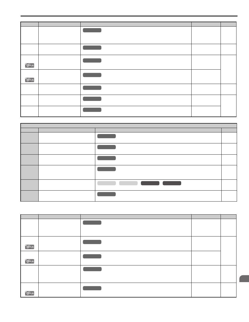
H4: Analog Outputs
H3-09
(417H)
Terminal A2 Signal Level
Selection
0: 0 to 10 V
1: –10 to 10 V
Note: Use DIP switch S1 to set input terminal A2 for a current or a voltage input signal.
Default: 0
Min: 0
Max: 0
H3-10
(418H)
Terminal A2 Function Selection
Sets the function of terminal A2.
Default: 0
Min: 0
Max: 1F
H3-11
(419H)
Terminal A2 Gain Setting
Sets the level of the input value selected in H3-10 when 10 V is input at terminal A2.
Default: 100.0%
Min: -999.9%
Max: 999.9%
H3-12
(41AH)
Terminal A2 Bias Setting
Sets the level of the input value selected in H3-10 when 0 V is input at terminal A2.
Default: 0.0%
Min: -999.9%
Max: 999.9%
H3-13
(41BH)
Analog Input Filter Time Constant
Sets a primary delay filter time constant for terminals A1 and A2. Used for noise filtering.
Default: 0.03 s
Min: 0.00 s
Max: 2.00 s
H3-16
(2F0H)
Offset for Terminal A1
Applies an offset to analog input A1. Can be used for zero adjustment of the analog input.
Default: 0
Min: -500
Max: 500
H3-17
(2F1H)
Offset for Terminal A2
Applies an offset to analog input A2. Can be used for zero adjustment of the analog input.
Default: 0
Min: -500
Max: 500
H3 Multi-Function Analog Input Settings (H3-02 and H3-10)
Setting
Function
Description (For when output is 100%)
Page
0
Speed Reference Bias
(value added to input signal when multiple
analog terminals supply the speed reference)
E1-04 (maximum output frequency)
2
Auxiliary Speed Reference 1
(used as a second speed reference)
E1-04 (maximum output frequency)
3
Auxiliary Speed Reference 2
(used as third speed reference)
E1-04 (maximum output frequency)
E
Motor Temperature (PTC thermistor input)
oH3 Alarm detection level: 1.18 V
oH4 Fault detection level: 2.293 V
14
Torque Compensation (load cell input)
10 V = Motor rated torque
1F
Not used (Through Mode)
Sets this value when the terminal is not used or when using the terminal in the pass-through mode
.
No.(Addr.)
Name
Description
Setting
Page
H4-01
(41DH)
Terminal FM Monitor Selection
Selects the data to be output through multi-function analog output terminal FM.
Set the desired monitor parameter to the digits available in U-. For example, enter “103”
for U1-03.
Default: 102
Min: 000
Max: 999
H4-02
(41EH)
Terminal FM Gain
Sets the signal level at terminal FM that is equal to 100% of the selected monitor value.
Default: 100.0%
Min: -999.9%
Max: 999.9%
H4-03
(41FH)
Terminal FM Bias
Sets the bias value added to the terminal FM output signal.
Default: 0.0%
Min: -999.9%
Max: 999.9%
H4-04
(420H)
Terminal AM Monitor Selection
Selects the data to be output through multi-function analog output terminal AM.
Set the desired monitor parameter to the digits available in U-. For example, enter “103”
for U1-03.
Default: 103
Min: 000
Max: 999
H4-05
(421H)
Terminal AM Gain
Sets the signal level at terminal AM that is equal to 100% of the selected monitor value.
Default: 50.0%
Min: -999.9%
Max: 999.9%
No.(Addr.)
Name
Description
Setting
Page
All Modes
common
_
All Modes
common
_
All Modes
common
_
All Modes
common
_
All Modes
common
_
All Modes
common
_
All Modes
common
_
All Modes
common
_
All Modes
common
_
All Modes
common
_
All Modes
common
_
common
_
CLV
CLV/PM
V/f
OLV
All Modes
common
_
All Modes
common
_
All Modes
common
_
All Modes
common
_
All Modes
common
_
All Modes
common
_