Refer to closed-loop crimp, D.2 ul standards, Closed-loop crimp terminal recommendations – Yaskawa L1000E AC Drive Technical Manual for CIMR-LE Models for Elevator Applications User Manual
Page 453: Table d.3 closed-loop crimp terminal size
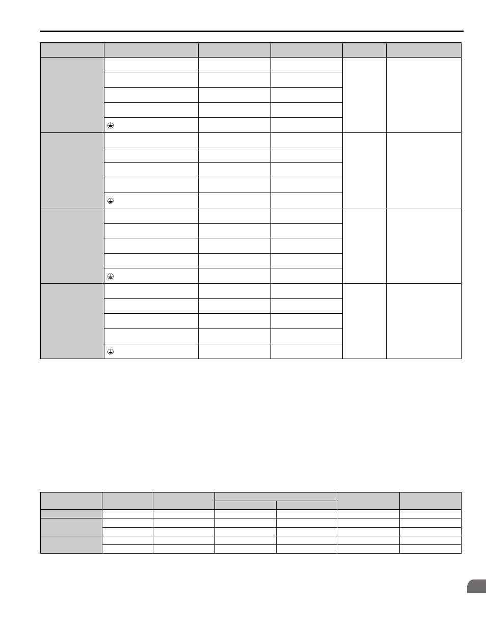
D.2 UL Standards
YASKAWA ELECTRIC SIEP YAIL1E 01A YASKAWA AC Drive L1000E Technical Manual
453
St
an
dar
d
s
Complianc
e
D
Note: Use crimp insulated terminals or insulated tubing for wiring these connections. Wires should have a continuous maximum
allowable temperature of 75
°C 600 V UL approved vinyl sheathed insulation. Ambient temperature should not exceed 40°C.
Closed-Loop Crimp Terminal Recommendations
Yaskawa recommends using closed-loop crimp terminals on all drive models. UL approval requires the use of UL Listed
crimp terminals when wiring the drive main circuit terminals on models 2A0106 to 2A0432 and 4A0056 to 4A0260. Use
only crimping tools as specified by the crimp terminal manufacturer. Yaskawa recommends crimp terminals made by JST
and Tokyo DIP (or equivalent) for the insulation cap.
matches the wire gauges and terminal screw sizes with Yaskawa - recommended crimp terminals, tools, and
insulation caps. Refer to the appropriate Wire Gauge and Torque Specifications table for the wire gauge and screw size
for your drive model. Place orders with a Yaskawa representatives the Yaskawa sales department.
Table D.3 Closed-Loop Crimp Terminal Size
4A0140
R/L1, S/L2, T/L3
95
(3/0)
50 to 95
(1/0 to 4/0)
M10
18 to 23
(159 to 204)
U/T1, V/T2, W/T3
70
(2/0)
50 to 95
(1/0 to 4/0)
–, +1
–
50 to 95
(1/0 to 4/0)
+3
–
25 to 95
(3 to 4/0)
25
(4)
25
(4)
4A0188
R/L1, S/L2, T/L3
95
(4/0)
50 to 95
(1/0 to 4/0)
M10
18 to 23
(159 to 204)
U/T1, V/T2, W/T3
95
(4/0)
50 to 95
(1/0 to 4/0)
–, +1
–
35 to 95
(1 to 4/0)
+3
–
50 to 95
(1/0 to 4/0)
25
(4)
25 to 35
(4 to 2)
4A0225
R/L1, S/L2, T/L3
50
× 2P
(1
× 2P)
35 to 150
(2 to 300)
M10
18 to 23
(159 to 204)
U/T1, V/T2, W/T3
70
× 2P
(1/0
× 2P)
35 to 150
(2 to 300)
–, +1
–
50 to 150
(1 to 250)
+3
–
25 to 70
(3 to 3/0)
25
(4)
25 to 150
(4 to 300)
4A0260
R/L1, S/L2, T/L3
70
× 2P
(2/0
× 2P)
95 to 300
(1 to 600)
M10
18 to 23
(159 to 204)
U/T1, V/T2, W/T3
70
× 2P
(2/0
× 2P)
95 to 300
(1/0 to 600)
–, +1
–
70 to 300
(3/0 to 600)
+3
–
35 to 185
(1 to 325)
35
(2)
35 to 185
(2 to 350)
Wire Gauge
Terminal Screws
Crimp Terminal
Model Number
Tool
Insulation Cap
Model No.
Code
Machine No.
Die Jaw
14 AWG
M4
R2-4
YA-4
AD-900
TP-003
100-054-028
12 / 10 AWG
M4
R5.5-4
YA-4
AD-900
TP-005
100-054-029
M5
R5.5-5
YA-4
AD-900
TP-005
100-054-030
8 AWG
M4
8-4
YA-4
AD-901
TP-008
100-054-031
M5
R8-5
YA-4
AD-901
TP-008
100-054-032
Drive Model
Terminal
Recomm. Gauge
AWG, kcmil
Wire Range
AWG, kcmil
Screw
Size
Tightening Torque
N•m (lb.in.)