A3 - 177 – Yaskawa PC NC User Manual
Page 417
A3 - 177
YASNAC PCNC Operating Manual
APPENDIX 3: Parameter Tables
1331
Error detect-ON area during spindle
loop control
0.001mm
0
255
1332
Error detect-ON area during spindle
loop control B
0.001mm
0
255
1351
Servo error range when spindle loop
control
%
0
255
Spindle, Multiplication
relative to rapid feed in
servo error range for
gear B
1352
Servo error range when spindle loop
control
%
0
255
Spindle, Multiplication
relative to rapid feed in
servo error range for
gear B
1416
Maximum spindle speed during
solid tap
r/min
0
32767
1417
Spindle position loop gain for solid
tap
0.01[1/S]
0
32767
1418
Spindle C-axis, max speed
corresponding to 10V
r/min
0
666
Maximum spindle
speed corresponding to
10 V of command (C-
axis is used)
1419
Spindle gear A base speed
r/min
0
32767
1435
Spindle, max speed corresponding
to 10V (Gear B)
r/min
0
32767
1436
Maximum spindle speed during
solid tap (Gear
B)
r/min
0
32767
1437
Spindle position loop gain for solid
tap (Gear B)
0.01[1/S]
0
32767
1439
Spindle gear B base speed
r/min
0
32767
1500
Solid tap servo shaft retraction
in-position width
0.001mm
0
32767
1502
Solid tap synchronization offset
parameter K1
-32767
32767
1503
Solid tap synchronization offset
parameter K2
-32767
32767
1506
Rotary tool spindle sync offset
parameter K1
-32767
32676
1507
Rotary tool spindle sync offset
permeate K2
-32767
32676
1510
No. of teeth of gear A on the spindle
side
tooth
0
32767
No. of teeth of gear A
on the spindle side for
spindle loop control
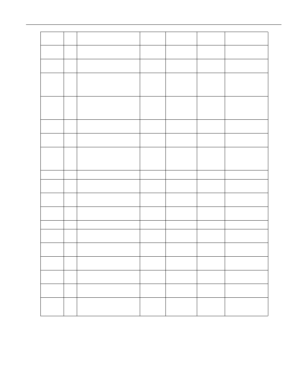
Address
Bit
Description
Register
Units
Minimum
Value
Maximum
Value
Long Description