Yaskawa PC NC User Manual
Page 168
4 - 6
YASNAC PCNC Operating Manual
Chapter 4: Maintenance
(2) Alarm Nos.: 2061 to 2068 (Reference Point Return Area Error)
(3) Alarm Nos.: 2071 to 2078, 2081 to 2088
(Reference Point Return Position Error)
Table 4.1.5.2: Troubleshooting - Alarm Nos.: 2061 to 2068 (Reference Point Return Area Error)
CAUSE CHECK
ITEM
COUNTERMEASURES
The reference
point return start
point is at the
zero point side of
the deceleration
limit switch.
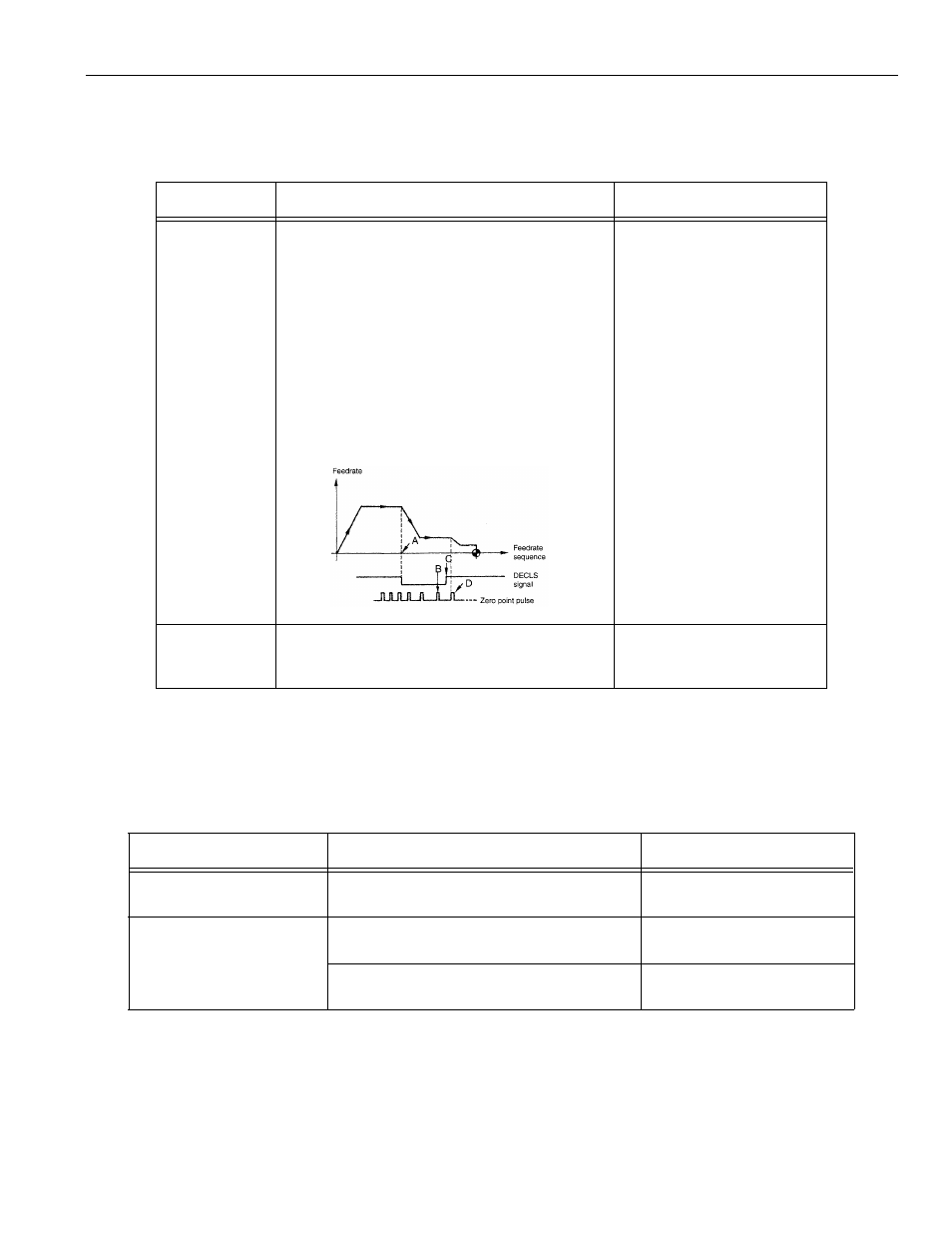
Deceleration limit switch (DECLS)
If reference point return is started from a point
located at the reference point side of DECL
(point C) as shown below, an alarm occurs.
Note: This error check is not made before the execution
of manual reference point return after the power
is turned ON.
Return the axis to a position on the
deceleration LS or away from it
and, then, execute reference
point return once again.
Approach
feedrate is
too fast.
Compare the setting for the approach
feedrate parameter with the parameter list.
Change the setting for
parameters pm2521 to pm2525
to an appropriate value.
Table 4.1.5.3: Troubleshooting – Alarm Nos.: 2071 to 2078, 2081 to 2088 (Reference Point Return
Position Error)
CAUSE CHECK
ITEM
COUNTERMEASURES
Alarm in manual reference
point return operation
Check if the error occurs every time.
Contact machine tool builder or
your Yaskawa representative.
Alarm in automatic reference
point return operation
G28: Check if the alarm occurs every time.
Contact machine tool builder or
your Yaskawa representative.
G27: Check the point specified in the program
if it agrees with the zero point.
Review the program.
#3073 DO (1st axis)
#3073 D1 (2nd. axis)
#3073 D2 (3rd axis)
#3073 D3 (4th axis)
#3073 D4 (5th axis)
Execute reference
point return again
while observing the
I/O signal monitor
screen