A3 - 11 – Yaskawa PC NC User Manual
Page 251
A3 - 11
YASNAC PCNC Operating Manual
APPENDIX 3: Parameter Tables
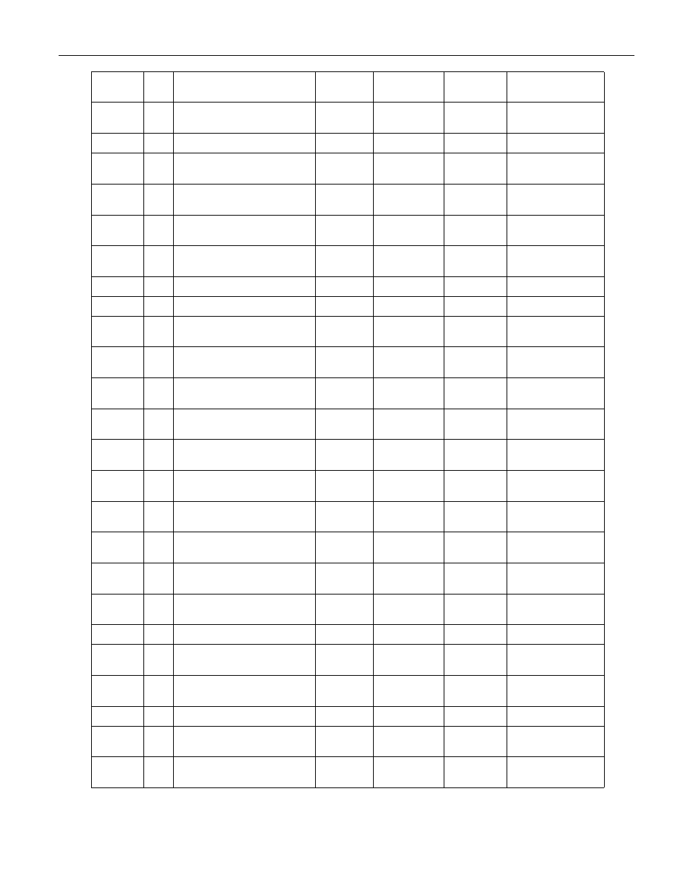
1145
2nd Servo axis automatic system
axis name
ascii
0
255
1322
2nd axis Error detect-ON area
0.001mm
0
255
1372
2nd axis Reduced vibration level
when servo stop
%
0
100
1552
2nd axis backlash compensation
amount
0.1micron
0
32767
1562
2nd axis No of teeth of monitor
when servo feed change
tooth
0
255
1572
2nd axis No of teeth of screw side
when servo feed change
tooth
0
255
1590
2nd axis Position loop gain Kp
0.01[1/S]
500
20000
1591
2nd axis Velocity loop gain Kv
0.1[1/S]
350
32767
1592
2nd axis Speed loop integration time
constant Ti
0.01msec
26
32767
1593
2nd axis Second position loop gain
Kp
0.01[1/S]
500
20000
1594
2nd axis Speed feed forward gain
Kvfff
%
0
100
1595
2nd axis Second velocity loop gain
Kv
0.1[1/S]
350
32767
1596
2nd axis First step axis torsion filter
time constant Tn
0.01msec
1
32767
1597
2nd axis Second step axis torsion
filter time
0.01msec
1
32767
1598
2nd axis Third step axis torsion fil-
ter time constant Tn
0.01msec
1
32767
1599
2nd axis Monitor board signal selec-
tion, multiplication
0
32767
1642
2nd axis Variable in position check
No1 area
0.001mm
0
32767
1652
2nd axis Variable in position check
No2 area
0.001mm
0
32767
For caned cycle and
solid tap
1672
2nd axis torque limit value (+)
%
0
32767
1682
2nd axis Servo Damping, observer
time
Hz
0
32767
1702
2nd axis Servo Damping, load iner-
tia fine adjust
%
0
10000
1712
2nd axis backlash time constant
0.01msec
0
32767
1752
2nd axis Servo Damping, high pass
filter time
const
micro sec
0
32767
1782
2nd axis contour compensation 2nd
coefficient
0.001times
0
32767
Address
Bit
Description
Register
Units
Minimum
Value
Maximum
Value
Long Description