H3C Technologies H3C MSR 50 User Manual
Page 229

4-34
Table 4-29 DIP switches and E1 interfaces of the FIC-E1/FIC-E1-F modules
Module
FIC-1E1/FIC-1E1-F
FIC-2E1/FIC-2E1-F
FIC-4E1/FIC-4E1-F
DIP
switch S1
S1 S2 S1 S2 S3 S4
Controlled E1
interface
Interface 0
Interface
0
Interface
1
Interfac
e 0
Interfac
e 1
Interfac
e 2
Interfa
ce 3
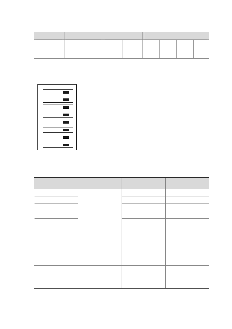
By default, all the DIP switch BITs are placed to the position of ON, as illustrated in the following figure:
Figure 4-41 Default setting of the DIP switches for the FIC-E1/FIC-E1-F modules
on
1
2
3
4
5
6
7
8
The following table describes how to set a DIP switch on the FIC-E1/FIC-E1-F modules:
Table 4-30 Setting DIP switches on the FIC-E1/FIC-E1-F modules
DIP switch
Description
Configuration of
75-ohm impedance
Configuration of
120-ohm impedance
1BIT ON
OFF
2BIT ON
OFF
3BIT ON
OFF
4BIT
ON OFF
5BIT
75-ohm/120-ohm toggle
switch
ON OFF
6BIT
RxRing grounding mode
switch
OFF: RxRing is grounded
using capacitance.
ON: RxRing is grounded
directly.
—
7BIT
RxShield grounding
switch
—
z
ON: RxShield is
grounded.
z
OFF: RxShield is not
grounded.
8BIT
RxShield grounding
mode switch
—
z
OFF: RxShield is
grounded using
capacitance.
z
ON: RxShield is
grounded directly.
