Interface cable, Connecting an interface cable, Table 3-5 – H3C Technologies H3C MSR 50 User Manual
Page 109

3-5
Table 3-5 LEDs of the XMIM-16FSW/XMIM-24FSW FE port
LED status
Description
Green LED (LINK)
z
ON: A link is present.
z
OFF: No link is present.
Yellow LED (ACT)
z
Blinking: Data is being received and sent on the port.
z
OFF: No data is being received or sent on the port.
XMIM-16FSW and XMIM-24FSW are both 1U (44.45 mm, namely, 1.75 in.) in height and each occupy
two slots (the upper slot and the lower slot).
Interface cable
10BASE-T, 100BASE-TX, and gigabit Ethernet interfaces are connected to Ethernet networks with
Ethernet cables, usually category-5 twisted pair cables.
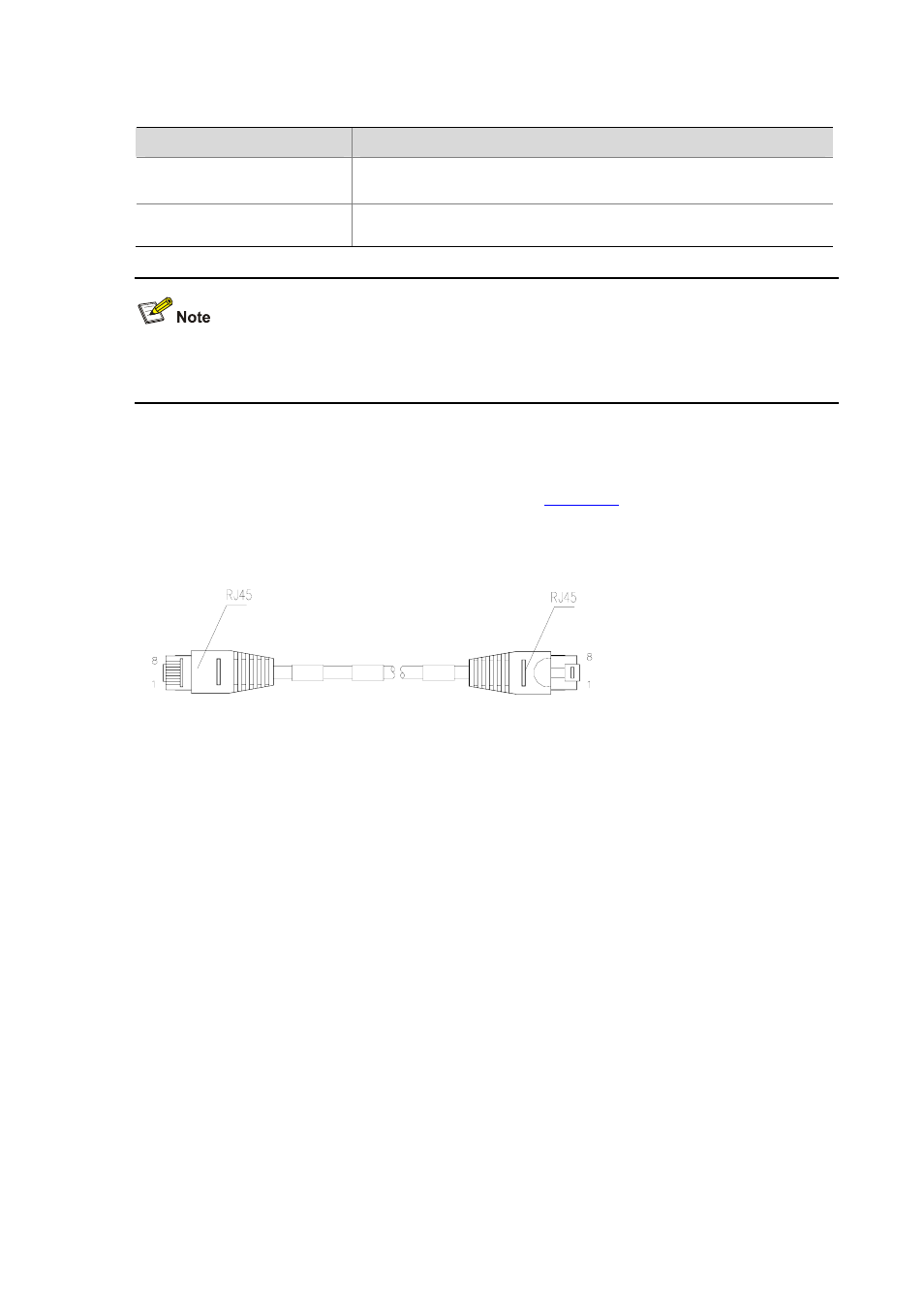
shows the appearance of an
Ethernet cable.
Figure 3-5 Ethernet cable
Ethernet cables fall into standard (straight-through) cables and crossover cables.
z
Standard cable: The sequences of colored wires at the two RJ-45 connectors crimped to the
twisted pair cable are completely the same. Standard cables are used to connect terminal devices
such as PC and router to hubs or LAN Switches.
z
Crossover cable: The sequences of colored wires at the two RJ-45 connectors crimped to the
twisted pair cable are different. Crossover cables are used to connect terminal devices such as PC
and router to terminal devices.
For the connection, identification, and preparation of these two types of cables, refer Low-End and
Mid-Range Series Routers Cable Manual
.
Connecting an interface cable
Follow the steps below to connect an interface cable:
1) To connect the router to a PC or another router, use a crossover cable. To connect the router to a
hub or LAN Switch, use a straight-through cable. Connect one end to an Ethernet interface of the
router and the other end to the PC, the other router, the hub, or the LAN switch.
2) Check the status of the LEDs on the panels after power-on. If the LINK LED is ON, a link is present.
If the LINK LED is OFF, no link is present and in this case you should check the line.
