Interface cable, Connecting the interface cable, Mim-1gef/mim-2gef – H3C Technologies H3C MSR 50 User Manual
Page 117: Introduction

3-13
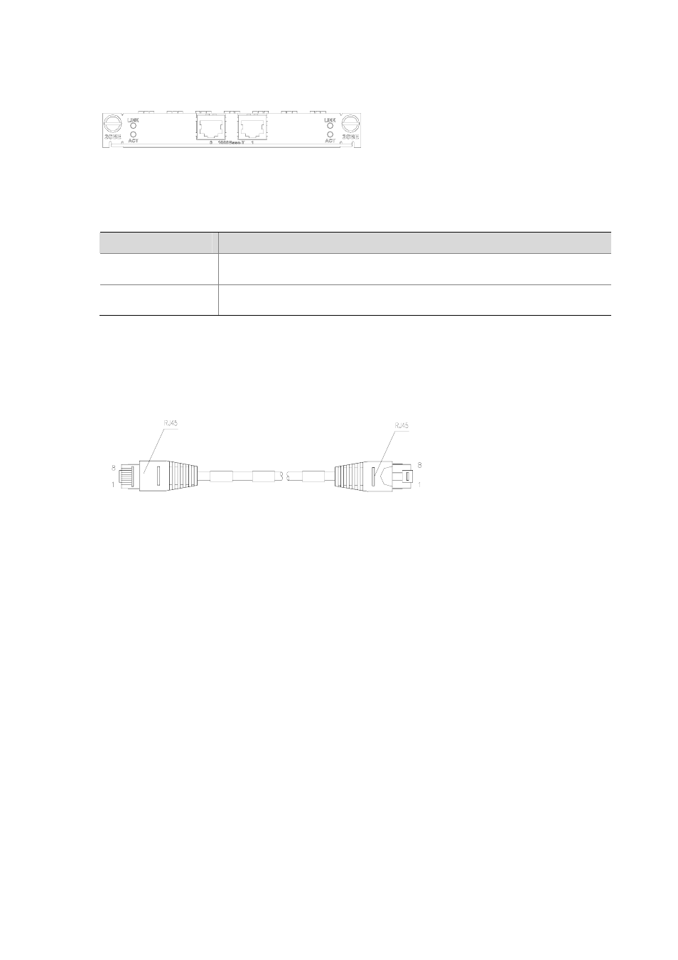
Figure 3-14 MIM-2GBE
The following table describes the LEDs on the MIM-1GBE/MIM-2GBE panel.
Table 3-13 Description of the LEDs on the MIM-1GBE/MIM-2GBE panel
LED
Description
LINK
z
OFF means no link is present;
z
ON means a link is present.
ACT
z
OFF means no data is being transmitted or received;
z
Blinking means data is being received or/and transmitted.
Interface cable
MIM-1GBE/MIM-2GBE uses both crossover and straight-through cables for connection.
Figure 3-15 Ethernet cable
For the pinouts of Ethernet cables, see Low-End and Mid-Range Series Routers Cable Manual.
Connecting the interface cable
To connect a PC or another router, use a crossover cable; to connect a LAN Switch or HUB, use a
straight-through cable.
Step1 Connect one end of the cable to the Ethernet port and the other end to the peer device;
Step2 Check the status of LINK LED on the 1GBE panel: ON means the link is connected and OFF means
the link is not connected. In the latter case, check the line.
MIM-1GEF/MIM-2GEF
Introduction
MIM-1GEF/MIM-2GEF is short for 1/2-port 1000Base-SX/1000Base-LX GE optical interface module,
where GE is short for Gigabit Ethernet and F for fiber, indicating optical fiber interface.
MIM-1GEF/MIM-2GEF is used for the communication between router and LAN.
MIM-1GEF/MIM-2GEF supports:
z
Five types of 1000Base-LX/1000Base-SX SFP removable modules: multi-mode short-haul (850
nm), single mode medium-haul (1310 nm), single mode long-haul (1310 nm), single mode
long-haul (1550 nm), and single mode ultra-long haul (1550 nm)
z
1000 Mbps interface rate
