AMETEK Lx Series II Programming Manual User Manual
Page 183
Programming Manual
Lx \ Ls Series II
179
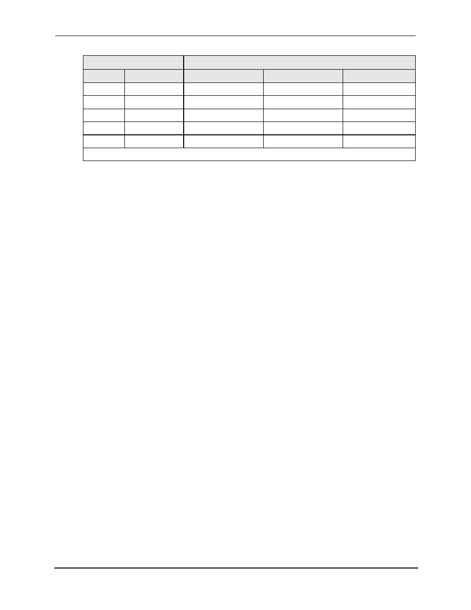
Command
Response (Fields separate by SPACE 0x20 characters)
Field A
Field B
Field C
TLK
PZM
PZMA000.0
B242.1
C118.9
TLK
REG0
(Contents of REG0)
TLK
RNG
RNGA 135.0
TLK
VLT
VLTA120.1
B119.8
C120.0
TLK
WVF
WVFA SNW
B SNW
C SNW (*)
Note (*)
If function is not enabled, a syntax Error message will be generated.
Table 8-5: Example TALK responses for 3 phase systems
To query the measured Voltage (TLK VLT)
VLT may be used as an argument to the header TLK with an A, B or C extension. When used as an
argument, it will set up the AC Power System to measure the output voltage with 0.1 volt resolution.
To query the measured Current (TLK CUR)
CUR may be used as an argument to the header TLK with an A, B or C extension. When used as
an argument, it will set up the AC Power System to measure the output current in amps.
To query the measured Power (TLK PWR)
PWR may be used as an argument to the header TLK with an A, B or C extension. When used as
an argument, it will set up the AC Power System to measure the output power in watts.
To query the measured Power Factor (TLK PWF)
PWF may be used as an argument to the header TLK with an A, B or C extension. When used as
an argument, it will set up the AC Power System to measure the output power factor from 0 to 1.000.
To query the measured Apparent Power (TLK APW)
APW may be used as an argument to the header TLK with an A, B or C extension. When used as
an argument, it will set up the AC Power System to measure the Apparent Power output in VA.
To query the measured Frequency (TLK FQM)
FQM may be used as an argument to the header TLK. There are no extensions for this argument.
When FQM is used as an argument, it will set up the AC Power System to measure the output
frequency in hertz.
To query the measured Phase Angle (TLK PZM)
PZM may be used as an argument with an extension A, B or C for the header TLK. When used as
an argument, PZM will set up the AC Power System to measure the phase angle of phase B and C
relative to phase A. The measurement is made at the External Sense terminals. Phase A is the
reference phase and will always be reported as 000.0 degrees unless the AC Power System is
operating in the external sync mode.