AMETEK Lx Series II Programming Manual User Manual
Page 140
Programming Manual
Lx \ Ls Series II
136
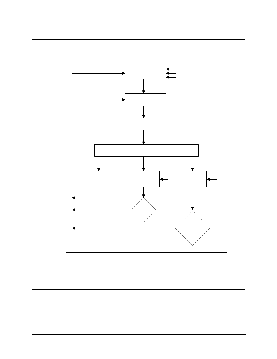
6.7.2 Output Trigger System Model
Figure 6-2 is a model of the output trigger system. The rectangular boxes represent states. The
arrows show the transitions between states. These are labeled with the input or event that causes
the transition to occur.
IDLE STATE
INITIATED STATE
DELAYING STATE
WAIT FOR SYNC STATE
OUTPUT
PULSE
CHANGES
OUTPUT
STEP
CHANGES
OUTPUT
LIST
CHANGES
PULSE
COUNT
DONE?
LIST
COMPLETE
OR
LIST:STEP ONCE
?
YES
NO
NO
YES
SYNC COMPLETED
DELAY COMPLETED
TRIGGER RECEIVED
INIT[:IMM]
ABOR
*RST
*RCL
INIT:CONT OFF
INIT:CONT ON
OR
LIST NOT COMPLETE &
LIST:STEP ONCE
Figure 6-2: Model of output trigger system.
6.7.3 Initiating the Output Trigger System
When the AC source is turned on, the trigger subsystem is in the idle state. In this state, the
trigger subsystem ignores all triggers. Sending the following commands at any time returns the
trigger system to the Idle state:
ABORt *RST *RCL