10 ape queries - tlk headers – AMETEK Lx Series II Programming Manual User Manual
Page 176
Programming Manual
Lx \ Ls Series II
172
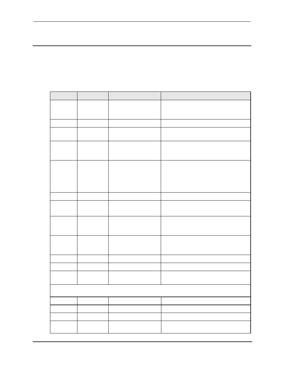
8.2.10 APE Queries - TLK Headers
The table below shows the APE TLK headers, the phase selection extension and available
arguments. If the phase extension(s) do not follow the header, the command will be applied to all
available phases.
The TLK header precedes all query commands in APE. This is the equivalent of the “?” query
termination in SCPI. Most settings can be queried by using the TLK header in conjunction with the
relevant programming command header, e.g. TLK AMP to query the voltage setting. The TLK
header is also used to query measurements.
Argument
Extension
Data returned
Definition
ALM
A
B
C
0000
*135.0
*270.0
Default voltage range code
Low Voltage Range
High Voltage Range
AMP
A, B, C
0 to 270.0
Programmed voltage Amplitude value in volts.
APW
A, B, C
0 to 6000 or
0.00 to 20.00
Output VA (3000Ls to 6000Ls)
Output KVA (All other models)
CFG
A
B
C
0 to 30
* 28
* 120
IEEE-488 Listen Address
Configuration Code
Phase C initial Value
CLM
A
B
C
MAX CURRENT
0 or 2
2 or 1
Defines the maximum current per phase (model
specific)
Defines the power measurement resolution decimal
point.
Defines the current measurement resolution decimal
point.
CRL
A, B, C
0 to MAX CURRENT
Programmed output current limit.
CUR
A, B, C
0.00 to 20.0
or
0.0 to 100.0
Output current (4500L-3P and 2750L-3P)
(All other models)
ELT
A
B
C
0000 to 9999
00 to 59
00 to 59
Total accumulated hours (H)
Accumulated minutes (M)
Accumulated seconds (S)
FLM
A
B
C
60
45
5000
Default frequency
Low frequency limit
High frequency limit
FQM
None
45.00 to 5000
Measured output frequency
FRQ
None
45.00 to 5000
Programmed frequency
INI
A
C
0000 to 005.0
O to CRL
Default voltage
Default current limit
(*)
Standard values shown. Values will be different for other ranges, output power and options.
NOTE:
If the A, B or C Extension is not sent with the argument, all phases will be reported.
SNC
None
INT or EXT
Programmed external sync mode
WVF
A, B, C
INT or EXT
Programmed waveform
PHZ
A, B, C
0.0 to 359.9
Programmed output phase angle
PWR
A, B, C
0 to 2000 or
Output watts (3000Ls to 6000Ls)
Output KW (All other models)