Camera connectors, Right side of camera – RED ONE OPERATION GUIDE User Manual
Page 22
Build 31 v31.6.16
NOVEMBER 28, 2011
© 2007-2011 RED.COM INC.
21
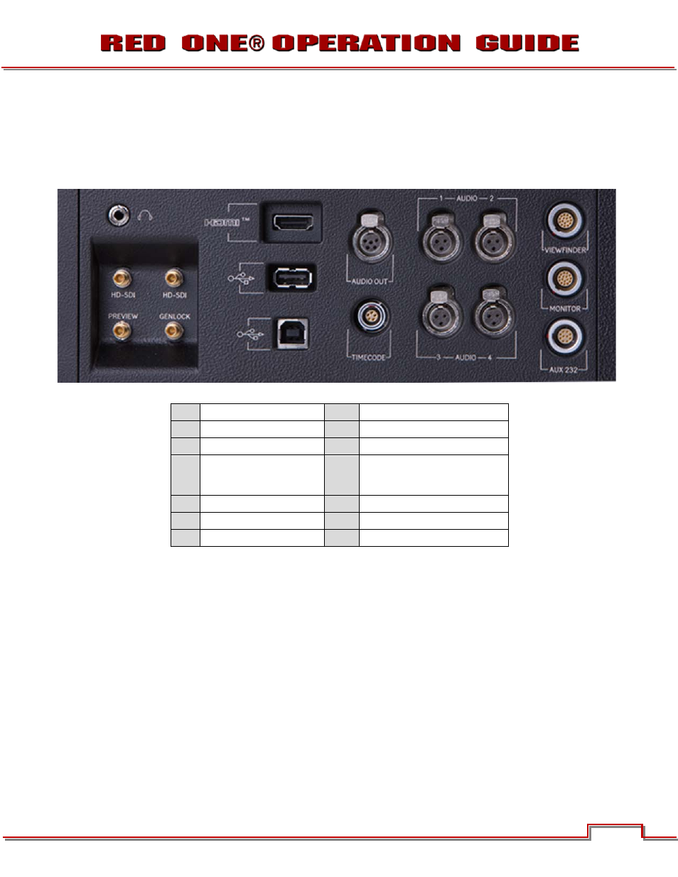
CAMERA CONNECTORS
RIGHT SIDE OF CAMERA
This section describes the physical connectors on the RED ONE camera body. For detailed description
APPENDIX D: INPUT/OUTPUT CONNECTORS
A
Headphone
H
USB Slave
B
Program HD-SDI (A)
I
Audio Out
C
Program HD-SDI (B)
J
Timecode
D
Preview HD-SDI
K
Audio In Ch 1 – 4 (1-2 Upper
Left - Right, 3-4 Lower Left -
Right)
E
Video Genlock
L
Viewfinder for RED EVF
F
HDMI Out
M
Monitor for RED LCD
G
USB Master
N
Aux / RS232
Figure 5 – Right Side Camera Connections
The right side of the camera contains all the video, audio and time code inputs and outputs.
From top left to bottom right, these comprise a
(A), and four DIN 1.0/2.3 video
(D) and
Next is an HDMI output (F), a
(G) to connect the camera to another camera or to connect a USB
memory device to update camera firmware, a
(H) to connect the camera to another
camera or computer based controller, a 5-pin mini-XLR audio output (I), a
(K). Finally there are two 16-pin push lock LEMO connectors (L, M) that pro-
vide video, communications and power for a
LEMO connector (N) supporting the
port that can interface to a variety of B4 lenses and lens
motor control devices.
One 6-inch length DIN 1.0 / 2.3 to BNC video adaptor cable and one 9-inch length 3-pin mini-XLR to mini-
XLR cable plus a mini-XLR to full size XLR adaptor are provided with the camera.
Additional video and audio adaptor cables may be ordered online at
A
B
C
D
E
F
G
H
I
J
K
L
M
N