Example: rhythmic vocoder (combination), Effect i/o, 732 example: rhythmic vocoder (combination) – KORG Electronic Keyboard User Manual
Page 742: Effect guide
Effect Guide
732
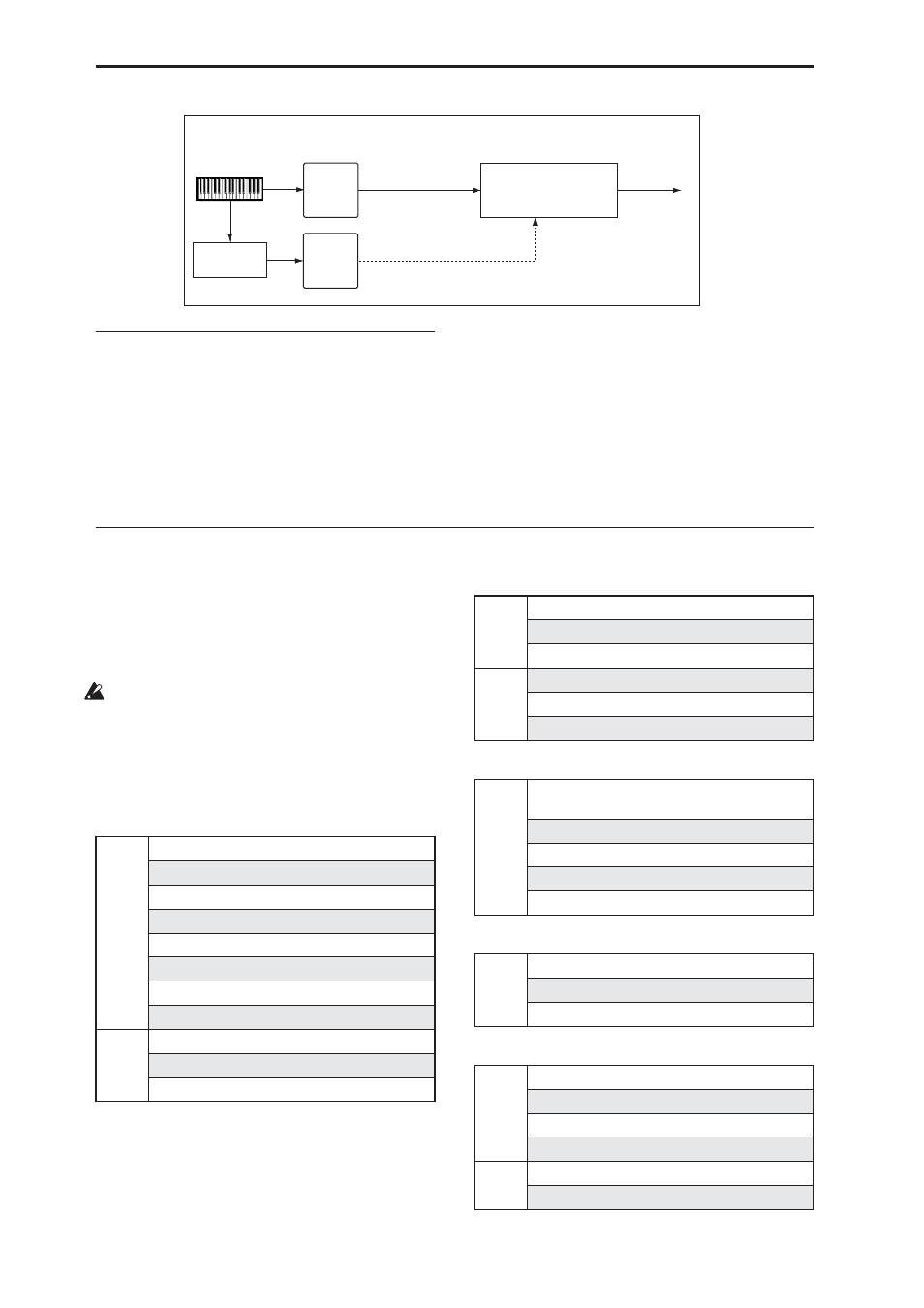
Example: Rhythmic Vocoder
(Combination)
Vocoder effects produce their distinctive sound by
using an audio signal (the modulator) to modulate a
different audio signal (the carrier). Although the most
common application of a vocoder is to use audio from
a mic as the modulator, you can also use a drum
pattern or similar signal as the modulator instead,
producing a rhythm vocoder effect.
In the example shown in the diagram, a drum pattern
generated by KARMA is sent to the FX Control bus
and used as the modulator for the vocoder.
For timbre 1 (the carrier), set Bus Select to IFX1,
sending the signal to IFX1: Vocoder. For timbre 2 (the
drum program we’re using as the modulator), set FX
Control Bus to FX Ctrl1, sending the signal to FX Ctrl1
bus. For IFX1: Vocoder, set “Modulator Source” to FX
Ctrl1 so that the timbre 2 signal will be the modulator
for the vocoder.
Effect I/O
To achieve the best tonal quality, signals sent to the
effects should be at the maximum level below clipping.
Also, use the Wet/Dry parameter for the Insert Effects,
Total Effects and the “Output Level” or “Return 1, 2”
parameter for the Master Effects to adjust the effect
output level.
If the input level is too low, the SN ratio may
decrease. On the other hand, if the input level is too
high, clipping may occur.
The Global Internal Headroom setting will also
change the maximum input level of the effect.
The following table shows the parameters related to
the level settings:
Program mode (HD-1)
Program mode (EXi: Common)
Program mode (AL-1)
Program mode (CX-3)
Combination mode/Sequencer mode
IFX1
026: Vocoder
Timbre1
: Pad
Bus Select
: IFX1
FX Control Bus
: FX Ctrl1
Modulator Source
: FX Control 1
Rhythmic Vocoder (Combination)
Bus Select
: L/R
(FX Control Bus1)
(Carrier)
(Modulator)
Timbre2
: Drums
KARMA
Drum pattern
Input
OSC1/2 MS1, 2, 3, 4 Level (P2)
Filter1/2 Input Trim (P3)
Filter1/2 Output Level (P3)
Driver1/2 Drive (P4)
Amp1/2 Amp Level (P4)
EQ Input Trim (P4)
Send1/2 (P8)
Effect Trim parameter
*1
(P8, P9)
Output
Effect Wet/Dry parameter (P8, P9)
Return1, 2 (P9)
Master Volume (P9)
Input
EQ Input Trim (P6)
Send1/2 (P8)
Effect Trim parameter
*1
(P8, P9)
Output
Effect Wet/Dry parameter (P8, P9)
Return1, 2 (P9)
Master Volume (P9)
Input
OSC Mixer Level (OSC1, OSC2, Sub OSC, Ring
Mod., Noise) (P4)
Filter1/2 Input Trim (P3)
Filter1/2 Output Level (P3)
Driver1/2 Drive (P4)
Amp1/2 Amp Level (P4)
Input
Expression Minimum, Level (P4)
Drawbar (P5)
Output Level (P7)
Input
Volume (P0)
Timbre EQ Input Trim (P1)
Send1/2 (P8)
Effect Trim parameter
*1
(P8, P9)
Output
Effect Wet/Dry parameter (P8, P9)
Return1, 2 (P9)