Exb-di option, Example connections, Exb-di option 1 – KORG Electronic Keyboard User Manual
Page 1051
Option boards/Memory/Calendar battery EXB-DI option
1041
EXB-DI option
The EXB-DI option provides an ADAT™ Compatible
Optical Output which digitally outputs the audio
signal from the OASYS, and also allows the digital
signal to be synchronized with another digital audio
device.
In this owner’s manual, “ADAT” is used as a general
designation for ADAT compatible multi-track
recorders such as the Alesis ADAT.
How audio outputs are related to ADAT output
channels
When the EXB-DI is installed, the eight ADAT output
channels correspond to Individual Out 1–8. If you
want to send the L/R output from ADAT outputs 1/2,
3/4, 5/6, or 7/8, make the desired setting in L/R Bus
Indiv. Assign (Global 0–2b).
Example connections
Digitally recording the sound of the OASYS to an
ADAT
1. Use an ADAT-Optical cable (sold separately) to
connect the OASYS’s ADAT OUT connector to the
ADAT’s Digital INPUT.
For connections, use an ADAT-Optical cable
manufactured by Alesis Corporation or an optical
cable for CD/DAT (both sold separately).
2. Set the OASYS’s System Clock (Global 0–1d) to
Internal.
3. Set the word clock source of the ADAT to “DIG
48K.”
For details, please refer to the ADAT’s manual.
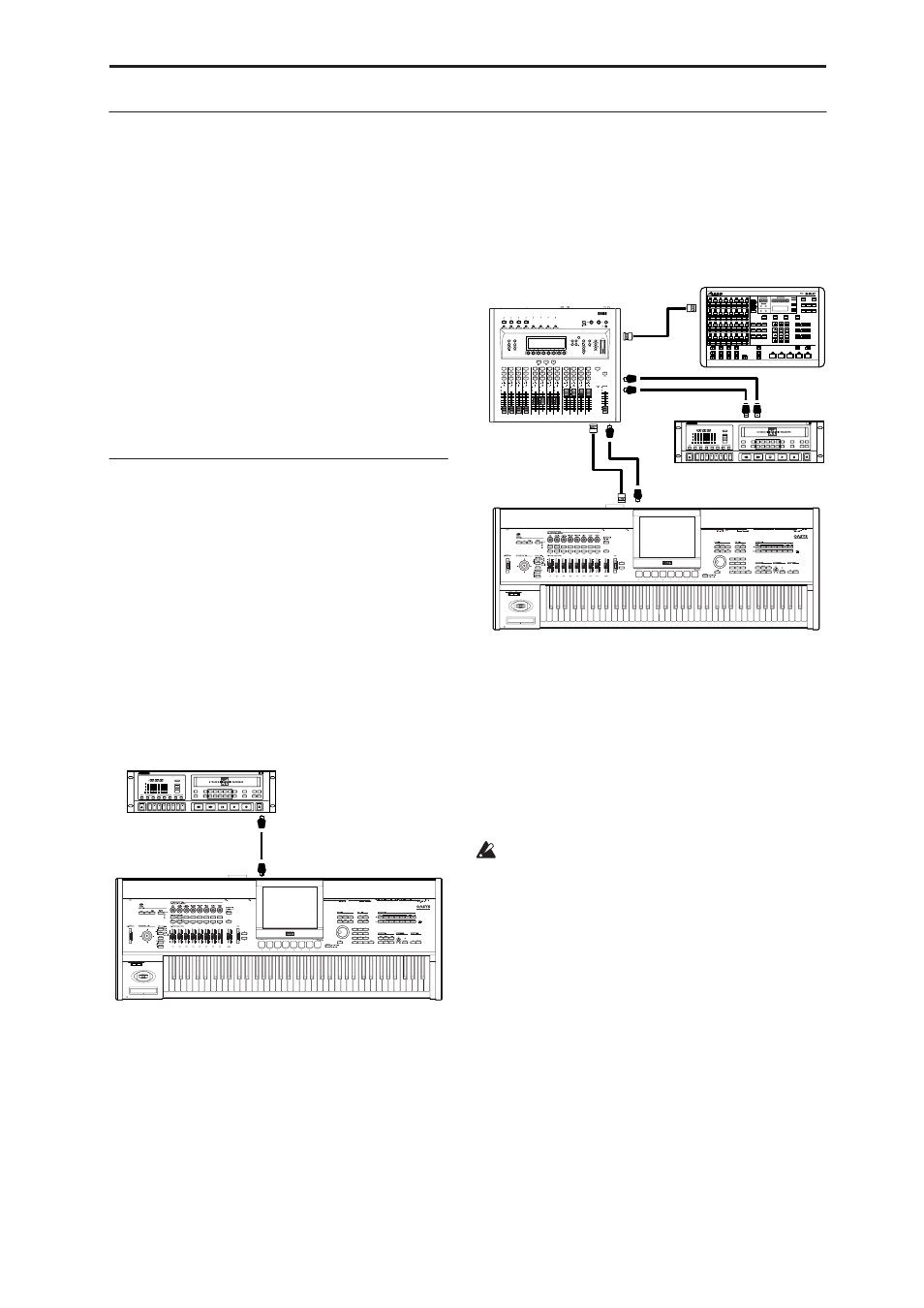
Complex setup with a Digital Mixer, ADAT, and
BRC
1. Use an ADAT-OPTICAL cable to connect the
OASYS’s ADAT output to the ADAT input of an
ADAT-compatible digital mixer.
2. Use ADAT-OPTICAL cables to connect the
respective inputs and outputs of the digital mixer
and the ADAT.
3. Make connections as shown in the following
diagram, so that an Alesis BRC Remote Controller
(or other digital audio device) can be used as the
master for digital signal synchronization, and
connect the WORD CLOCK output of the mixer to
the WORD CLOCK input of the OASYS.
For connections, use a BNC Coax cable made by Alesis
Corporation or a BNC cable made for video (both sold
separately).
4. Set the OASYS’s System Clock (Global 0–1d) to
Word Clock.
The OASYS will now use the WORD CLOCK input
as its master audio clock.
Note: If you wish to store the System Clock setting, use
the Write Global Setting utility to write it.
5. Set the word clock source of the ADAT to “DIG
48K.”
For details, please refer to the ADAT’s manual.
If the clock cannot be detected correctly due to a
disconnected BNC cable or for some other reason, a
error message “CLOCK ERROR !” will appear in
the LCD. If this occurs, check whether a problem
has occurred with the BNC cable.
If System Clock has been written as Word Clock,
the same error message will be displayed when the
OASYS is powered-on if the correct clock is not
being input.
DIGITAL IN
ADAT OUT
ADAT
OASYS
DIGITAL IN
WORD CLOCK OUT
WORD
CLOCK OUT
ADAT
OPTICAL IN
WORD CLOCK IN
WORD
CLOCK IN
ADAT OUT
DIGITAL IN
DIGITAL OUT
DIGITAL OUT
Digital Mixer
ADAT
ADAT BRC
OASYS