2c: manual 1, 2d: manual 2, 3: filter modulation – KORG Electronic Keyboard User Manual
Page 275: E information, see “5-2c: manual 1,” below, 5–2: page menu commands
Program P5: Filter 5-3: Filter Modulation
265
Intensity
[–99…+99]
This controls the depth and direction of the Mode 1-2
Crossfade modulation.
Intensity Mod AMS
[List of AMS Sources]
This selects an AMS source to modulate the intensity of
the main Mode 1-2 Crossfade AMS.
For instance, you can set AMS to use one of the LFOs,
and then set the Intensity Mod AMS to JS -Y. You can
then use the joystick to modulate the amount of the
LFO.
Intensity
[–99…+99]
This controls the depth and direction of the Intensity
Mod AMS.
5-2c: Manual 1
These parameters let you create your own mix of the
filters. When Mode 1 is set to Manual 1, it will use
these settings.
You may wonder why Band Reject is not included
here. This is because it’s not a filter mode per se.
Instead, it’s created by an equal combination of High
Pass and Low Pass. Try it and see!
Lowpass
[–99…+99]
This controls the volume of the Lowpass filter output.
Negative values invert the phase.
Highpass
[–99…+99]
This sets the volume of the Highpass filter output.
Bandpass
[–99…+99]
This controls the volume of the Bandpass filter output.
Dry
[–99…+99]
This sets the volume of the dry signal.
5-2d: Manual 2
The Manual 2 parameters are identical to those of
Manual 1, as described above.
▼ 5–2: Page Menu Commands
The number before each command shows its ENTER +
number-key shortcut. For more information on these
shortcuts, see “ENTER + 0-9: shortcuts for menu
commands” on page 138.
• 0: Write Program. For more information, see “Write
• 1: Exclusive Solo. For more information, see
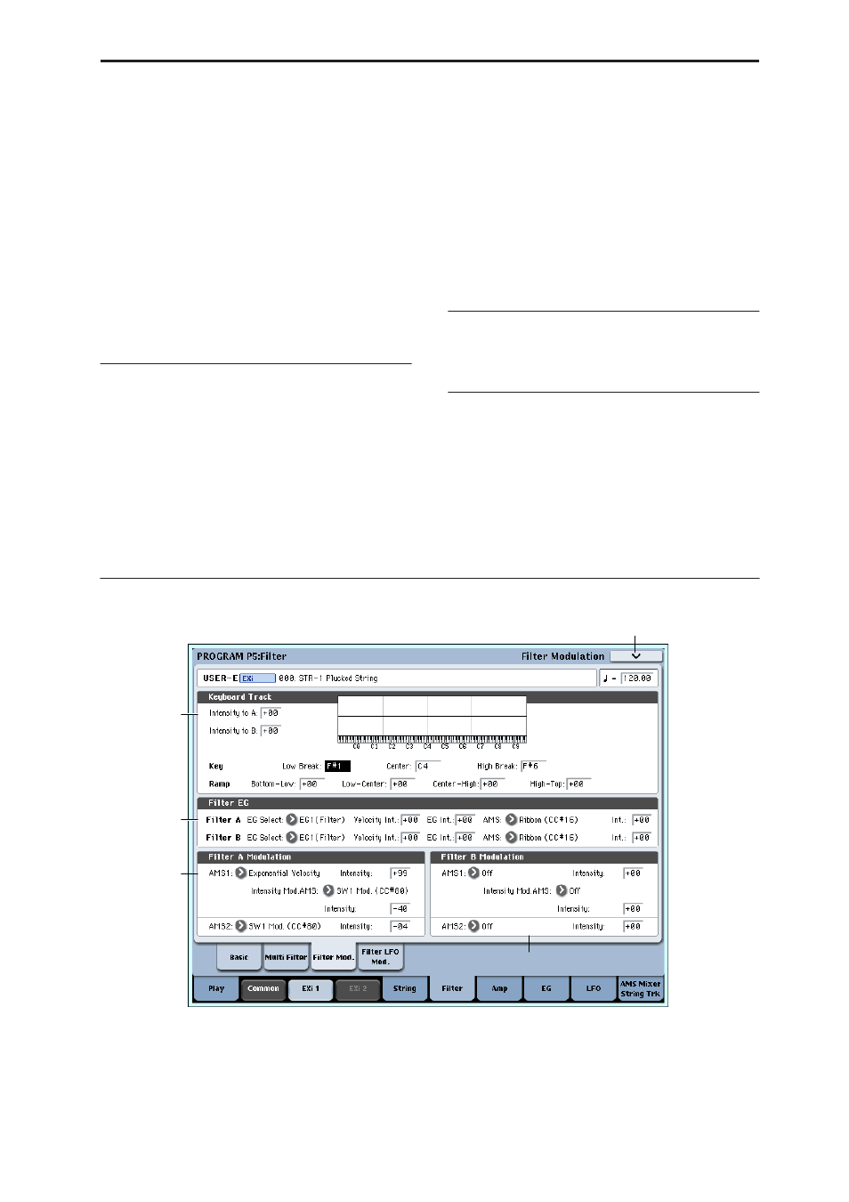
5-3: Filter Modulation
This page contains all of the settings for Filter
Frequency modulation (except for the LFOs, which are
on their own page). Among other things, you can:
• Set up complex keyboard tracking shapes, and
control how the tracking affects filter cutoff.
• Control the effect of the Filter Envelope on filter
cutoff.
• Assign AMS modulation for filter cutoff.
Filter B is available when the Filter Routing is set to
Serial or Parallel. Otherwise, the parameters for Filter
B will be grayed out.
5–3PMC
5–3a
5–3b
5–3c
5–3c