Lsi53c1030 pci configuration space address map – Avago Technologies LSI53C1030 User Manual
Page 88
4-2
PCI Host Register Description
Version 2.2
Copyright © 2001, 2002, 2003 by LSI Logic Corporation. All rights reserved.
Interrupts, and PCI-X) to optimize device performance. The LSI53C1030
does not hard code the location and order of the PCI extended capability
structures. The address and location of the PCI extended capability
structures are subject to change. To access a PCI extended capability
structure, follow the pointers held in the Capability Pointer registers and
identify the extended capability structure with the Capability ID register
for the given structure.
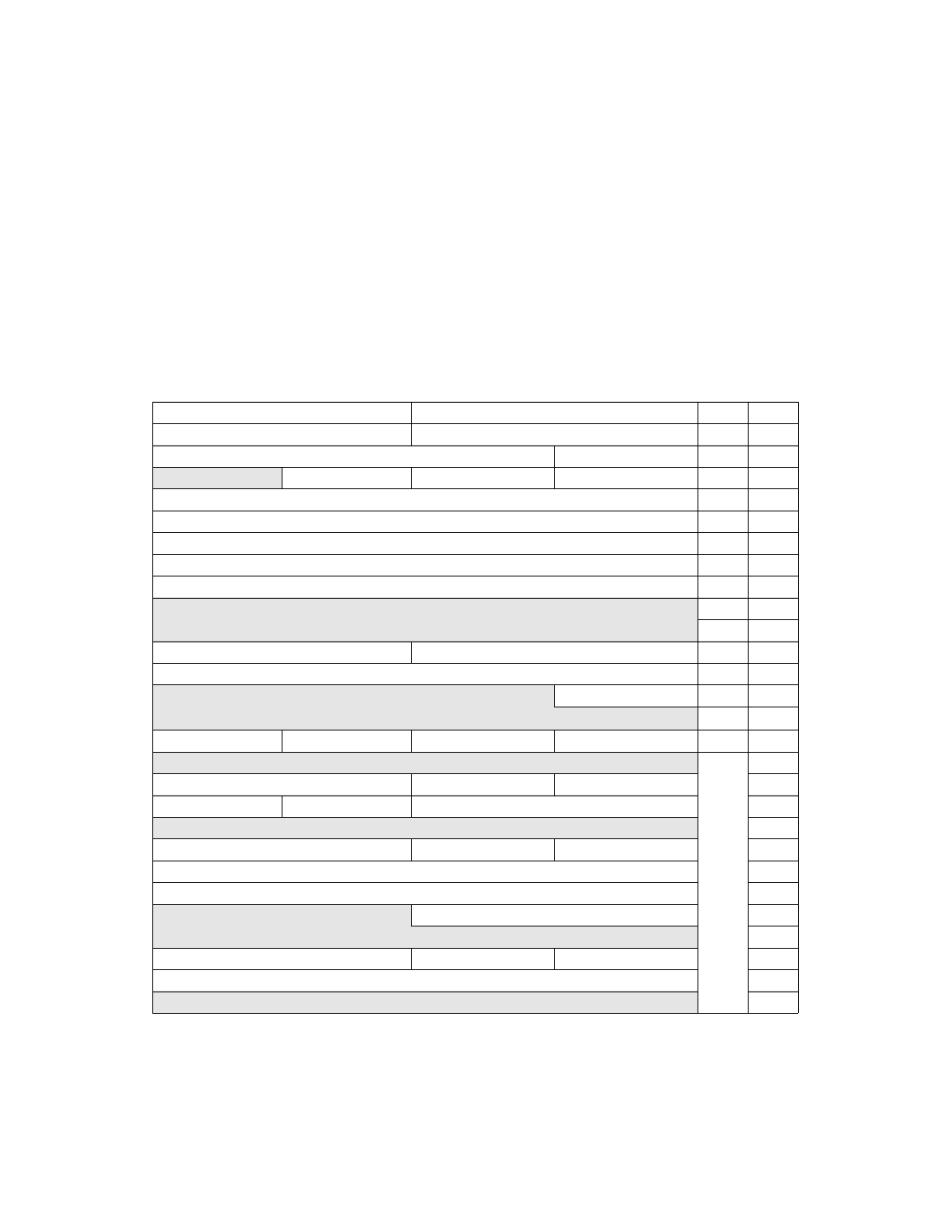
Table 4.1
LSI53C1030 PCI Configuration Space Address Map
31
16 15
0 Offset
Page
0x00
0x04
0x08
Reserved
0x0C
0x10
0x14
0x18
0x1C
0x20
Reserved
0x24
–
0x28
–
0x2C
0x30
Reserved
0x34
0x38
–
0x3C
Reserved
0x40–
0x7F
–
PM Next Pointer
PM Capability ID
PM Data
PM BSE
Power Management Control/Status
Reserved
–
MSI Capability ID
Reserved
–
PCI-X Capability ID
Reserved
–