Table 3.14 serial eeprom interface pins, 6 zero channel raid interface, Table 3.15 zcr configuration pins – Avago Technologies LSI53C1030 User Manual
Page 76: Zero channel raid interface, Serial eeprom interface pins, Zcr configuration pins, Section 3.6, “zero channel raid interface
3-16
Signal Description
Version 2.2
Copyright © 2001, 2002, 2003 by LSI Logic Corporation. All rights reserved.
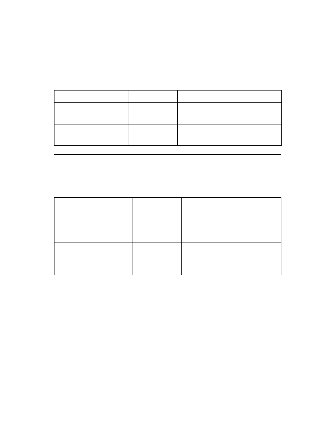
describes the serial EEPROM Interface signals.
3.6 Zero Channel RAID Interface
describes the zero channel RAID (ZCR) configuration signals.
Table 3.14
Serial EEPROM Interface Pins
Signal Name
BGA Position
Type
Strength Description
SerialCLK
J25
O
8 mA
Serial EEPROM clock. This signal requires a
4.7 k
Ω
external pull up resistor when an
EEPROM is present.
SerialDATA
H26
I/O
8 mA
Serial EEPROM data. This signal requires a
4.7 k
Ω
external pull up resistor when an
EEPROM is present.
Table 3.15
ZCR Configuration Pins
Signal Name
BGA Position
Type
Strength Description
ZCR_EN/
N23
I
N/A
This signal enables and disables ZCR
support on the LSI53C1030. By default,
this signal is internally pulled HIGH to
disable ZCR operation. Pull this signal
LOW to enable ZCR operation.
IOPD_GNT/
AC5
I
N/A
When ZCR is enabled on the LSI53C1030
the device only responds to PCI
configuration cycles if IOPD_GNT/ or
IDSEL is asserted. Connect IOPD_GNT/ to
PCI GNT/ on the external I/O processor.