8 gpio and led signals, Table3.18 gpio and led signals, Gpio and led signals – Avago Technologies LSI53C1030 User Manual
Page 79: Section 3.8, “gpio and led signals
GPIO and LED Signals
3-19
Version 2.2
Copyright © 2001, 2002, 2003 by LSI Logic Corporation. All rights reserved.
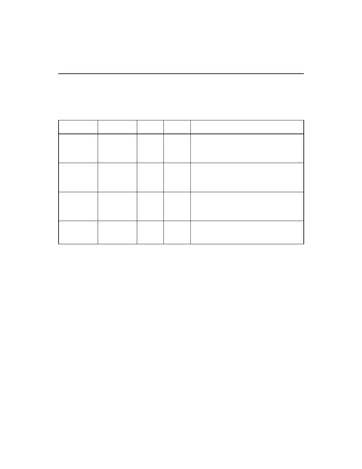
3.8 GPIO and LED Signals
describes the GPIO and LED signals group.
Table 3.18
GPIO and LED signals
Signal Name
BGA Position
Type
Strength Description
GPIO[7:0]
K25, L23,
L25, M25,
H25, K24,
AE25, AC23
I/O
8 mA
General purpose I/O pins. The LSI53C1030
controls these signals and can configure them
as inputs or as outputs. These pins default to
input mode after chip initialization.
A_LED/
J23
O
12 mA
A_LED/ either drives the SCSI Channel [0]
activity LED or provides a General Purpose
I/O pin. A_LED can be controlled by firmware
or driven by chip activity.
B_LED/
K23
O
12 mA
B_LED/ either drives the SCSI Channel [1]
activity LED or provides a General Purpose
I/O pin. B_LED/ can be controlled by firmware
or driven by chip activity.
HB_LED/
C25
O
12 mA
Firmware blinks Heart Beat LED at a
1.0 second interval when the IOP is
operational.
- MGA-725M4 (4 pages)
- MGA-71543 (4 pages)
- MGA-71543 (3 pages)
- MGA-82563 (6 pages)
- 3ware 9690SA-8I (Channel) (380 pages)
- 3ware SAS 9750-8i (48 pages)
- 3ware 9690SA-8I (Channel) (138 pages)
- 3ware SAS 9750-8i (29 pages)
- 3ware 9550SXU-8LP (Channel) (149 pages)
- 3ware 9550SXU-8LP (Channel) (40 pages)
- 3ware 9650SE-8LPML (Channel) (45 pages)
- 3ware 9690SA-8I (Channel) (27 pages)
- 3ware 9690SA-8I (Channel) (361 pages)
- 6160 SAS Switch (2 pages)
- Cache Protection for RAID Controller Cards (13 pages)
- MegaRAID SAS 9271-8iCC (13 pages)
- MegaRAID SAS 9361-8i (13 pages)
- MegaRAID SAS 9266-8i (12 pages)
- MegaRAID SAS 9380-8e (43 pages)
- Cache Protection for RAID Controller Cards (139 pages)
- MegaRAID SAS 9285-8ecv (80 pages)
- MegaRAID SAS 9285-8ecv (92 pages)
- MegaRAID SAS 9266-8i (20 pages)
- MegaRAID SAS 9271-8iCC (26 pages)
- MegaRAID SafeStore Software (502 pages)
- MegaRAID SAS 0260CV-4i (72 pages)
- MegaRAID SAS 0260CV-4i (64 pages)
- MegaRAID SAS 0260CV-4i (49 pages)
- MegaRAID SAS 9271-8i (8 pages)
- MegaRAID SAS 9361-8i (7 pages)
- MegaRAID SAS 9341-8i (8 pages)
- MegaRAID SAS 9380-4i4e (7 pages)
- MegaRAID SAS 9380-8e (7 pages)
- MegaRAID SAS 0260CV-4i (28 pages)
- MegaRAID SAS 9240-8i (4 pages)
- MegaRAID SAS 9280-24i4e (14 pages)
- MegaRAID SAS 9280-24i4e (16 pages)
- MegaRAID SAS 9260-16i (12 pages)
- MegaRAID SAS 9260-8i (4 pages)
- MegaRAID SafeStore Software (8 pages)
- MegaRAID SAS 9280-8e (22 pages)
- MegaRAID SAS 9261-8i (4 pages)
- MegaRAID SAS 9285-8e (12 pages)
- MegaRAID SAS 9280-16i4e (12 pages)
- MegaRAID SAS 9280-4i4e (4 pages)