Physical features, Installation – Wavetronix Click 400 (900 MHz radio) (CLK-400) - User Guide User Manual
Page 185

184
CHAPTER 22 • CLICK 250
Physical Features
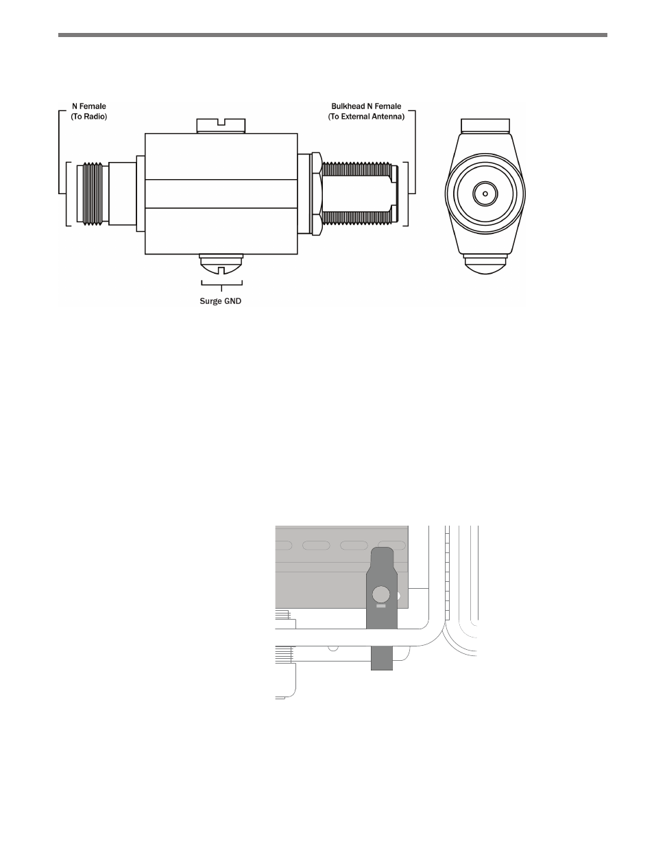
Figure 22.2 – Diagram of the Click 250
The Click 250 is a bulkhead N-Female to N-Female connector; both connector ports are
equally protected. The ground lug and terminal are located directly on the housing of the
Click 250.
Installation
The Click 250 should be mounted in the wall (usually the bottom) of a cabinet, in a 5/8” hole.
Wavetronix fiberglass cabinets come with such holes predrilled; aluminum cabinets do not
and a hole will need to be drilled. It is recommended that the hole be in the bottom of the
cabinet, on the far right.
x
GND
Click! 250
Figure 22.3 – Click 250 in Wall of Cabinet
Follow the steps below to install a Click 250.
1 Connect a 12 AWG stranded copper grounding wire to the surge GND bolt, as shown
below. There are two bolts on the Click 250; use the bolt with the rounded top.
- Click 421 (bluetooth to serial converter) (CLK-421) - User Guide Click 342 (lean managed ethernet switch) (CLK-342) - User Guide Click 341 (lean managed ethernet switch) (CLK-341) - User Guide Click 340 (lean managed ethernet switch) (CLK-340) - User Guide Click 331 (unmanaged ethernet switch) (CLK-331) - User Guide Click 330 (unmanaged ethernet switch) (CLK-330) - User Guide Click 304 (RS-232 to RS-485 converter) (CLK-304) - User Guide Click 305 (RS-232 to RS-485 converter) (CLK-305) - User Guide Click 301 (serial to ethernet converter) (CLK-301) - User Guide Click 100 (16 output contact closure) (CLK-100) - User Guide Click 104 (4-channel DIN rail contact closure) (CLK-104) - User Guide Click 110 (4-channel contact closure eurocard) (CLK-110) - User Guide Click 112 (detector rack card) (CLK-112) - User Guide Click 114 (detector rack card) (CLK-114) - User Guide Click 120 (screw terminal relay) (CLK-120) - User Guide Click 121 (spring cage relay) (CLK-121) - User Guide Click 200 (surge suppression) (CLK-200) - User Guide Click 201 (1 amp AC to DC converter) (CLK-201) - User Guide Click 202 (2 amp AC to DC converter) (CLK-202) - User Guide Click 203 (UPS and battery) (CLK-203) - User Guide Click 204 (4 amp AC to DC converter) (CLK-204) - User Guide Click 210 (AC circuit breaker) (CLK-210) - User Guide Click 211 (AC outlet) (CLK-211) - User Guide Click 221 (DC surge protector) (CLK-221) - User Guide Click 222 (system surge protector) (CLK-222) - User Guide Click 223 (dual-485 surge protector) (CLK-223) - User Guide Click 230 (AC surge protector) (CLK-230) - User Guide Click 250 (wireless surge protector) (CLK-250) - User Guide
